This thread has been locked.

If you have a related question, please click the "Ask a related question" button in the top right corner. The newly created question will be automatically linked to this question.

TIDA-00643: Controller getting heated

Part Number: TIDA-00643
Other Parts Discussed in Thread: BOOSTXL-DRV8305EVM, DRV8305, LMR16006, TMS320F28027F

Greetings.

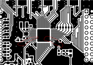
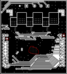
                    We have fabricated TIDA-00643 reference board and all the components which were given in the BOM file were soldered on to the board except LED and TVS diode. 

                     Lab2c was made run on the board and everything was working fine. But, the board was heating alot ( upto 70°C ) when given the speed reference value as 2.0(Q value -24) . The controller was getting heated after the user parameter identification step was under process (55 °C)

                     I have tried lowering the system clock frequency and EPWM clock frequency but there was barely any significant change in thermal behaviour

Please help.

  • Hello Natsu,

    How much current are you driving in the motor? What supply voltage are you using?

    Thanks,

    Matt

  • Hello Matt,

    The Supply voltage was 12V from SMPS and was drawing a current of 0.20A while motor identification step was under process.

    The phase current was measured to be 0.6A when RoverL identification step was under process, and was measured to be 30-60uA from RampUp - Rampdown steps. The current was measured using a multimeter.

    Thanks.

  • Hello Natsu,

    Thanks for the information. The voltage and current you are seeing on your end does not seem to concerning. One thing I would check is to ensure that the devices PowerPad is connected to the PCB with a good sized ground pour.

    A large copper plane will help disperse a lot of the heat from the IC, this tends to be a common issue with smaller board sizes. We have had other users comment on using heat sinks if their applications do not allow them to increase the board size or change the size of their copper thickness or size. Have you had other board iterations to check if temperature was an issue in the other ones?

    Best,

    Isaac

  • Hello Isaac,

    Thanks for the information. The copper thickness of the TIDA board that was fabricated is 35um. Please tell me how would that affect the board thermal behavior if we increase the thickness to 105um.

    Yes, there were other iterations of the board where we faced the same problem with thermal behavior.

    Can you please guide me on how to ensure that the device PowerPad is connected to the PCBwith a good ground pour.

    Thanks.

  • Can you please explain how the TVS diode(TPD4E05U06QDQA) actually works. Would the diode play any part in controlling thermal behaviour of the diode. It has not been soldered.

  • Hello Natsu,

    Here are some examples of the connecting the PCB with a good ground pour. These images are from the BOOSTXL-DRV8305EVM.

    This is from the top layer and you can see that the ground is connected via polygon ground pours. These layers are stitched together with another ground layer as seen in the image below:

    The two circles show on the pins are just to demonstrate that it is a ground pour based on the connections to the LaunchPad which correspond to the ground pins. Having larger planes like this help dissipate head better, in smaller boards is not always an option to have larger planes but including additional layers or a heat sink may be an option. The stitching helps create shorter ground loops as well which help reduce parasitic inductance on the board. 

    The TVS diode is used for ESD protection, it does not play a part in the thermal behavior of the DRV8305.

    Best,

    Isaac

  • Hello Issac

    Thank you so much for explaining it in fine detail.

    However, when the motor is running on speed reference control, the mosfets and gate driver DRV8305 look fine and are not heating at all.

    The problem is with the thermal behaviour of LMR16006 section and the microcontroller only.

    So, i have tried removing the LRM16006 section which converts 12V to 3.3V and connect 3.3V directly to the microcontroller and then the controller was not heating at all. So, could it be that the problem was with the LMR16006 section only?

    Thanks.

  • Hello Natsu,

    Thank you for the clarification, I was under the impression the problem was with the motor driver. If the overheating problem is occurring on the LMR16006 and TMS320F28027F portions of the board then I think it is definitely worth it to look into the LMR16006 since this is what is providing the 3.3V to the controller.

    I would recommend to make another post on the forum specifically for the LMR16006, unfortunately I am mostly familiar with the motor driver but this will get an expert that works with these buck regulators assigned to your issue and should be able to help you figure out what the problem is with the buck circuit on your board. Feel free to let me know if you have any other issues!


    Best,

    Isaac

  • Alright Issac,

    Thank you so much for your patience.

    I will raise another issue regarding the buck regulator then.

    Thanks.

  • No worries Natsu, always glad to help out. Let me know if you have any additional questions.

    Best,

    Isaac