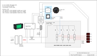
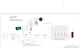
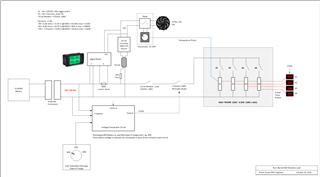
This thread has been locked.

If you have a related question, please click the "Ask a related question" button in the top right corner. The newly created question will be automatically linked to this question.

Voltage comparator design for EV battery discharge device

Other Parts Discussed in Thread: TLV6703, TLV1805

Hello,

Application:   

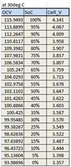
I am building a high power resistive load to discharge an EV battery which can vary 116Vdc to 93Vdc, depending on the state of charge (SoC). Attached chart showing relation between EV battery voltage and SoC.

Typically I would manually shutoff the discharge once it reached 20% or 30% SoC.

For my idea, I want it to automatically stop discharging at a predetermined voltage or SoC, so I dont have to babysit this.


> What I think design requires. (I'm not a electrical designer but here is what I think I need.)


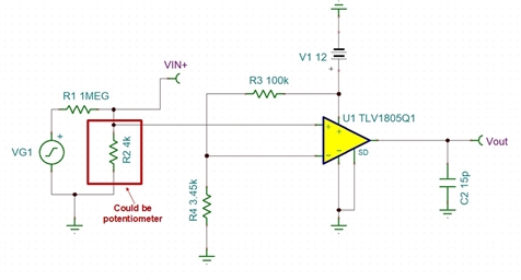
I believe this requires a voltage comparator circuit. comparing the EV battery high voltage versus a predetermined SoC voltage.

Then once both voltages are equal, the output of opamp drives a contactor to open the resistive load ?


Since the SoC setting can vary, depending on the user or situation, I don't know how you would vary the SoC voltage setting.

Also, since the EV battery is high voltage, the resistor devider network should be high in value to reduce high current flow ?

Thank you

  • Hello Bruce,

    You are right about needing a resistor divider network like the one used in the app note I am providing. I believe the "Undervoltage Protection With Hysteresis" section will help you with your application in the How To Protect 48-V Batteries from Overcurrent and Undervoltage app note. Do you want the output of the comparator to drive a FET to disconnect the load from the supply? If so, I can provide how to do that as well.

    Kind Regards,

    Joe

    All information in this correspondence and in any related correspondence is provided “as is” and “with all faults”, and is subject to TI’s Important Notice (www.ti.com/.../important-notice.shtml)

  • Hi Joe, thanks for your assistance.  
    I was thinking of using a contactor rated for 100A, which has a 12Vdc input to drive it. I have a DCDC converter in my design which converts the 100Vdc to 12Vdc. This 12V is used to power an auto radiator fan to cool resistor load, and to also power up a panel mount multimeter to measure voltage and current.
    I'm attaching my design if you want to check it. Could you share the FET design ?
    How do you determine over current discharge limit for a battery ?
    Many thanks !


  • Bruce,

    These are great questions. Joe will get back to you soon. Thank you for your patience.

    -Chi

  • Hi Bruce,

    I have a couple of follow-up questions for you.

    Is there a way you can show me where in your block diagram you would like to use the comparator?

    I am assuming you would like to control the switches S1 through S4. Do you have particular switches in mind? Depending on the switch you could control the switches with the output of the comparator. 

    Kind Regards,

    Joe

    All information in this correspondence and in any related correspondence is provided “as is” and “with all faults”, and is subject to TI’s Important Notice (www.ti.com/.../important-notice.shtml)

  • Hi Joe,

    I updated the schematic to show where I think the comparator circuit and contactor would go. The contactor would normally be closed, and the driver output of comparator would be 12Vdc, forcing contactor to open circuit.


    Switches S1-S4 are just manual SPST and usually all resistors are engaged and will nominally draw about 50A total.

    Hope this helps.  Thanks

  • Hi Joe, I added the user interface where the SoC is selected. Not sure how this would be done, perhaps another voltage divider setup ?

  • Hi Bruce,

    I am thinking of a couple of options:

    1. Use the TLV6703 with internal 400mV reference.
      1. Divide the monitored voltage down to where desired SoC = 400mV 
        1. This does save you the hassle of creating an external divider to create your reference.
      2. You would need an external Pull-Up resistor for this device.
      3. The potentiometer would just need to be placed on the battery voltage resistor divider.
    2. If you don't want a predefined reference value, then I would recommend the TLV1805 with push-pull outputs.
      1. It can operate from the same 12V and divide its supply for the reference. Please see the schematic below to see my proposed TLV1805 solution.
      2. The reference voltage was set to 400mV.
      3. R3 or R4 in this image could also be the potentiometer (Only for the TLV1805).

    The only changes needed to use the TLV6703 would be adding an external pull-up resistor, the potentiometer would have to be on the battery voltage divider (R1 or R2), and there is only one, non-inverting input to the device. I have provided the TLV6703 block diagram below.

    Please let me know if you need any clarification on the above and if either of these solutions work for you. I hope this helps!

    Kind Regards,

    Joe

    All information in this correspondence and in any related correspondence is provided “as is” and “with all faults”, and is subject to TI’s Important Notice (www.ti.com/.../important-notice.shtml)

  • Hi Joe, thank you for the information, its going to take me some time to understand it. How long can I keep this case open for ?

    Thank you

  • Bruce

    Theoretically we keep things open for as much as 13 days.  We will just send a reminder note in a week or so to keep it refreshed.  So take your time and best of luck with your design.

    Chuck

  • Bruce

    Just following up to make sure you want us to keep this thread open still.

    Chuck

  • Hi Chuck,  Please close this, I think a solution was provided.  Will I still be able to review the history ?  Thank you

  • Thanks Bruce and yes, you can save the link to this thread or search for the title in the future and the information will still be there.

    Chuck