This thread has been locked.

If you have a related question, please click the "Ask a related question" button in the top right corner. The newly created question will be automatically linked to this question.

TIDA-01063: TIDA-01063

Part Number: TIDA-01063

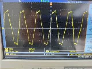
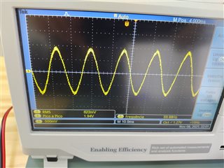
Hi, I work on enterprise dedicated to design device for smart grid. Currently I am developing a product based on TIDA-01063, however I observed distorted output signal and error of 20 %. I would like to know if our own TIDA-01063 is working correctly and how aquire eval board made by TI to check appropriate signals. 

  • Hi Fransergio,

    Can you share the waveforms you are getting for your board? Do you know if any modifications were made on your design that may be causing this perhaps? I can take a look at your design as well and see if there are any issues I can spot, so let me know and we can do that Via email.

    -Brian

  • Hi Brian, thanks for attention. No changes were made in original project. Gerber files and BOM list was sent to China where board and rugowski PCB were

    built. Above are two photos: bench for tests and distorted output. 


    When PCI board cascading with an integrator in this way: signal from rugoswki->integrator->TIDA-01063, signal improves its form as photo above. Although output signal becomes better, FFT indicates harmonic presence yet.

  • Hi Fransergio,

    Thanks for the provided information. Can you tell me what harmonic frequencies are present when doing the FFT? The Rogowski coil will replicate any fault conditions or harmonics present in the primary portion of the test setup, so I want to make sure we eliminate any issues with the test setup first.

    -Brian