Hi,
I'm new to using PSPICE-for-TI and have been struggling to get the simulation working.
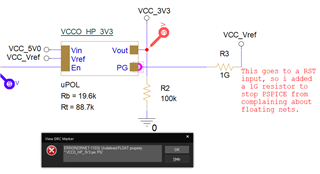
I have the PG pin of one SMPS connected to the EN pin of the next, but the second SMPS won't come up, even though it's enable pin is asserted.
Can someone please help me get this working?
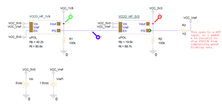
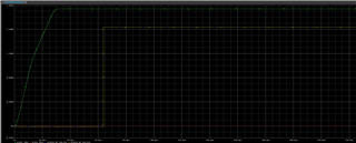
In addition, both SMPS's come up with the wrong voltage. I know from the physical board that the voltages are correct but PSICE seems to be displaying 1.93V for the 1.8V supply and also the wrong value for the 3.3V supply when it works. To get the 3.3V supply working, I need to disconnected it's enable pin from the 1.8V PG pin and instead connect it directly to VCC_Vref.
I'm happy to upload the project if somebody can tell me which files are needed. Otherwise, I hope the screenshots will help.
Schematic - Main
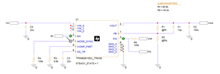
Schematic - SMPS
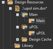
Schematic List
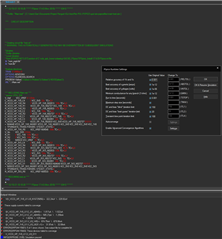
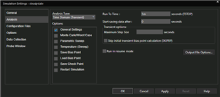
Simulation Settings
Simulation
Kind regards,
Dan