

Dear team:
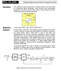
My client refers to the theoretical introduction of Solarlib.pdf in the TIDM-02008 project:
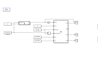
Simulink simulation parameters:
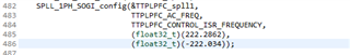
TTPLPFC_AC_FREQ: 50Hz, TTPLPFC_CONTROL_ISR_FREQUENCY, lpf_b0 and lpf_b1 parameters are consistent with the parameters used by TIDM-02008.

Simulink simulation results: input an AC signal with a frequency of 51Hz (a frequency that may appear in a 50Hz AC grid), and see if the waveform can be locked, and it is found that the fo output frequency and q axis cannot be stabilized.
function [sin_a,cos_a,fo_out,Q_out] = fcn(acValue,acFreq,isrFrequency,isrFrequencyMAX,lpf_b0,lpf_b1)

persistent sine;
if isempty(sine)
    sine = 0.0;
end
sin_a = sine;

persistent cosine;
if isempty(cosine)
    cosine = 0.0;
end
cos_a = cosine;

persistent cnt;
if isempty(cnt)
    cnt = 0.0;
end

persistent fn;
if isempty(fn)
    fn = acFreq;
end

persistent delta_t;
if isempty(delta_t)
    delta_t = 1.0/isrFrequency;
end

persistent osg_coeff_osg_k;
if isempty(osg_coeff_osg_k)
    osg_coeff_osg_k = 0.5;
end

persistent osg_coeff_osg_x;
if isempty(osg_coeff_osg_x)
    wn = 2.0 * 3.14159265 * fn;
    osg_coeff_osg_x = 2.0 * osg_coeff_osg_k * wn * delta_t;
end

persistent osg_coeff_osg_y;
if isempty(osg_coeff_osg_y)
    wn = 2.0 * 3.14159265 * fn;
    osg_coeff_osg_y = wn * delta_t * wn * delta_t;
end

persistent osg_coeff_osg_b0;
if isempty(osg_coeff_osg_b0)
    osg_coeff_osg_b0 = osg_coeff_osg_x / (osg_coeff_osg_x + osg_coeff_osg_y + 4.0);
end

persistent osg_coeff_osg_b2;
if isempty(osg_coeff_osg_b2)
    osg_coeff_osg_b2 = -osg_coeff_osg_x / (osg_coeff_osg_x + osg_coeff_osg_y + 4.0);
end

persistent osg_coeff_osg_a1;
if isempty(osg_coeff_osg_a1)
    osg_coeff_osg_a1 = 2 * (4.0 - osg_coeff_osg_y) / (osg_coeff_osg_x + osg_coeff_osg_y + 4.0);
end

persistent osg_coeff_osg_a2;
if isempty(osg_coeff_osg_a2)
    osg_coeff_osg_a2 = (osg_coeff_osg_x - osg_coeff_osg_y - 4) / (osg_coeff_osg_x + osg_coeff_osg_y + 4.0);
end

persistent osg_coeff_osg_qb0;
if isempty(osg_coeff_osg_qb0)
    osg_coeff_osg_qb0 = osg_coeff_osg_k * osg_coeff_osg_y / (osg_coeff_osg_x + osg_coeff_osg_y + 4.0);
end

persistent osg_coeff_osg_qb1;
if isempty(osg_coeff_osg_qb1)
    osg_coeff_osg_qb1 = 2 * osg_coeff_osg_k * osg_coeff_osg_y / (osg_coeff_osg_x + osg_coeff_osg_y + 4.0);
end

persistent osg_coeff_osg_qb2;
if isempty(osg_coeff_osg_qb2)
    osg_coeff_osg_qb2 = osg_coeff_osg_k * osg_coeff_osg_y / (osg_coeff_osg_x + osg_coeff_osg_y + 4.0);
end

persistent lpf_coeff_b0;
if isempty(lpf_coeff_b0)
    lpf_coeff_b0 = lpf_b0;
end

persistent lpf_coeff_b1;
if isempty(lpf_coeff_b1)
    lpf_coeff_b1 = lpf_b1;
end

persistent u_0;
if isempty(u_0)
    u_0 = 0.0;
end
persistent u_1;
if isempty(u_1)
    u_1 = 0.0;
end
persistent u_2;
if isempty(u_2)
    u_2 = 0.0;
end

persistent osg_u_0;
if isempty(osg_u_0)
    osg_u_0 = 0.0;
end
persistent osg_u_1;
if isempty(osg_u_1)
    osg_u_1 = 0.0;
end
persistent osg_u_2;
if isempty(osg_u_2)
    osg_u_2 = 0.0;
end

persistent osg_qu_0;
if isempty(osg_qu_0)
    osg_qu_0 = 0.0;
end
persistent osg_qu_1;
if isempty(osg_qu_1)
    osg_qu_1 = 0.0;
end
persistent osg_qu_2;
if isempty(osg_qu_2)
    osg_qu_2 = 0.0;
end

persistent u_Q_0;
if isempty(u_Q_0)
    u_Q_0 = 0.0;
end
Q_out = u_Q_0;
persistent u_Q_1;
if isempty(u_Q_1)
    u_Q_1 = 0.0;
end

persistent u_D_0;
if isempty(u_D_0)
    u_D_0 = 0.0;
end

persistent ylf_0;
if isempty(ylf_0)
    ylf_0 = 0.0;
end
persistent ylf_1;
if isempty(ylf_1)
    ylf_1 = 0.0;
end

persistent fo;
if isempty(fo)
    fo = 0.0;
end
fo_out = fo;
persistent theta;
if isempty(theta)
    theta = 0.0;
end


if cnt >= isrFrequencyMAX
    cnt = cnt - isrFrequencyMAX;

    % Update the spll_obj->u[0] with the grid value
    u_0 = acValue;

    % Orthogonal Signal Generator
    osg_u_0 = osg_coeff_osg_b0 * (u_0 - u_2) + osg_coeff_osg_a1 * osg_u_1 + osg_coeff_osg_a2 * osg_u_2;

    osg_u_2 = osg_u_1;
    osg_u_1 = osg_u_0;

    osg_qu_0 = osg_coeff_osg_qb0 * u_0 + osg_coeff_osg_qb1 * u_1 + osg_coeff_osg_qb2 * u_2 + osg_coeff_osg_a1 * osg_qu_1 + osg_coeff_osg_a2 * osg_qu_2;

    osg_qu_2 = osg_qu_1;
    osg_qu_1 = osg_qu_0;

    u_2 = u_1;
    u_1 = u_0;

    % Park Transform from alpha beta to d-q axis
    u_Q_0 = cosine * osg_u_0 + sine * osg_qu_0;
    u_D_0 = cosine * osg_qu_0 - sine * osg_u_0;

    % Loop Filter
    ylf_0 = ylf_1 + lpf_coeff_b0 * u_Q_0 + lpf_coeff_b1 * u_Q_1;
    ylf_1 = ylf_0;

    u_Q_1 = u_Q_0;

    fo = fn + ylf_0;

    theta = theta + (fo * delta_t) * (2.0 * 3.1415926);
    if theta < 0
        theta = 0;
    end
    if(theta > (2.0 * 3.1415926))
        theta = theta - (2.0 * 3.1415926);
        %theta = 0;
    end

    sin_a = sin(theta);
    cos_a = cos(theta);

    sine = sin_a;
    cosine = cos_a;
end

cnt = cnt + 1;
simulink simulation result q-axis output:
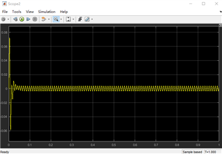
Output frequency:

May I ask why this is caused?
In the table for calculating lpf_b0 and lpf_b1, what does the specific meaning of "Error Band" mean?
Best regards
