This thread has been locked.

If you have a related question, please click the "Ask a related question" button in the top right corner. The newly created question will be automatically linked to this question.

TIDM-02009: Questions about the Resolver-to-Digital solution

Part Number: TIDM-02009
Other Parts Discussed in Thread: TIDA-01527

Hi team, 

There are couple of questions about the RDC solution in TIDM-02009, please give some guidance, thanks. 

1. What's the function of the sampling circuit for excitation signal and the half of the VREF? There is no related initialization code in the project. 


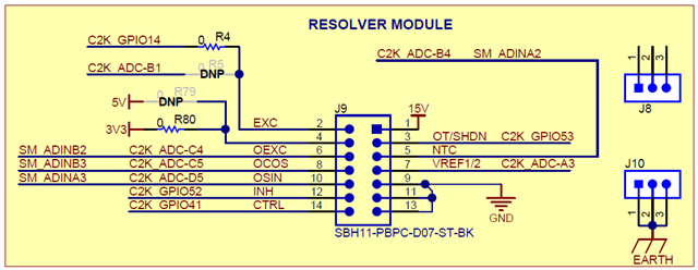
2. What is the function of the Analog MUX/DEMUX circuit? Is it necessary or optional?

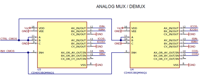
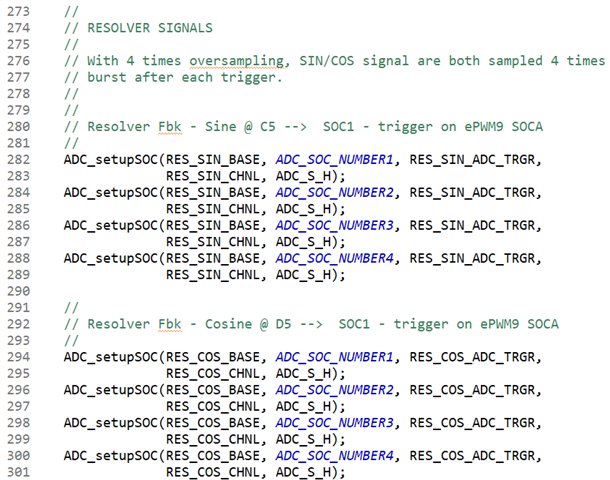
According to the initialization code in the project, I think it is just a analog switch? 

3. Do we have simulation model for the filter circuit in the EXC PWM path? 

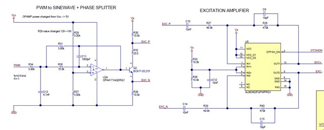
4. Do we have recommended scheme for fault diagnosis on the circuit of Sin/Cos/Exc PWM? 

Please give some guidance. Thanks.

Best Regards,

Will Gao 

  • Hi Will,

    Please find answers below:

    1. EXC signal is an output sent from DAC / PWM to generate execration signal for resolver. OESC is excitation feedback, which is optional signal reserved for diagnostic use case. It is not being used in functional code only. Similar thing to VREF1/2. This signal was put there for mid-voltage check in diagnostic function (optional). Zero calibration can be done at start-up time before excitation signal being sent out on SIN/COS feedback.

    2. This is optional. For detail of this circuit, please refer to TIDA-01507.

    3. I do not have one personally. I will check with team to see if there is any simulation model. BTW, we have a new design of excitation circuit using ALM2403 in next implementation, which simplified the circuit. 

    For diagnostic function implementation and the new ALM2403 circuit, we can discuss offline via email. Thanks.

    Best regards,

    Han Zhang

  • Hi Han, 

    Thanks for your reply. I have checked the TIDA-01527 and have studied the principle for Analog MUX circuit. It can be used to reduce the system error: 

    Please help on checking if there is simulation model for the excitation circuit. Thanks again. 

    Best Regards, 

    Will Gao 

  • Hi Will,

    The owner of TIDA-01507 is on vacation for now. I will get back to you once he returns. Thanks.

    Han

  • Hi Will,

    We do not have anything simulation model that we can share publicly. The design owner of TIDA-01527 will contact you offline to follow up with this case. I will close this thread. Thanks.

    Han