This thread has been locked.

If you have a related question, please click the "Ask a related question" button in the top right corner. The newly created question will be automatically linked to this question.

TIDA-01063: TIDA-01063, TIDA-00777

Part Number: TIDA-01063
Other Parts Discussed in Thread: TIDA-00777,

Hi Guys,

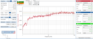
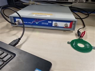
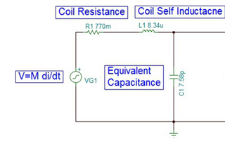
1. It is mentioned in the application note ( TIDUBV4A) that  Self resistance, Inductance, and capacitance of the Rogowski coil is 0.77ohms, 8.34uH & 7.56pF but whereas when I measure from my network analyzer the resistance value comes around few 11-15ohms, and the capacitance value also does not match. could you please let me know your measurement procedure?

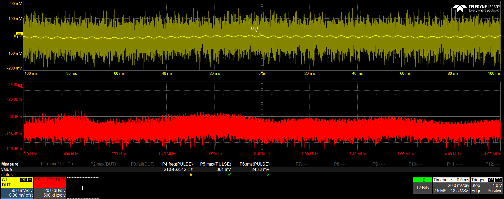
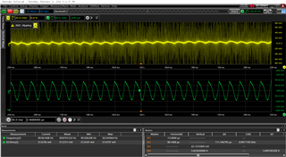
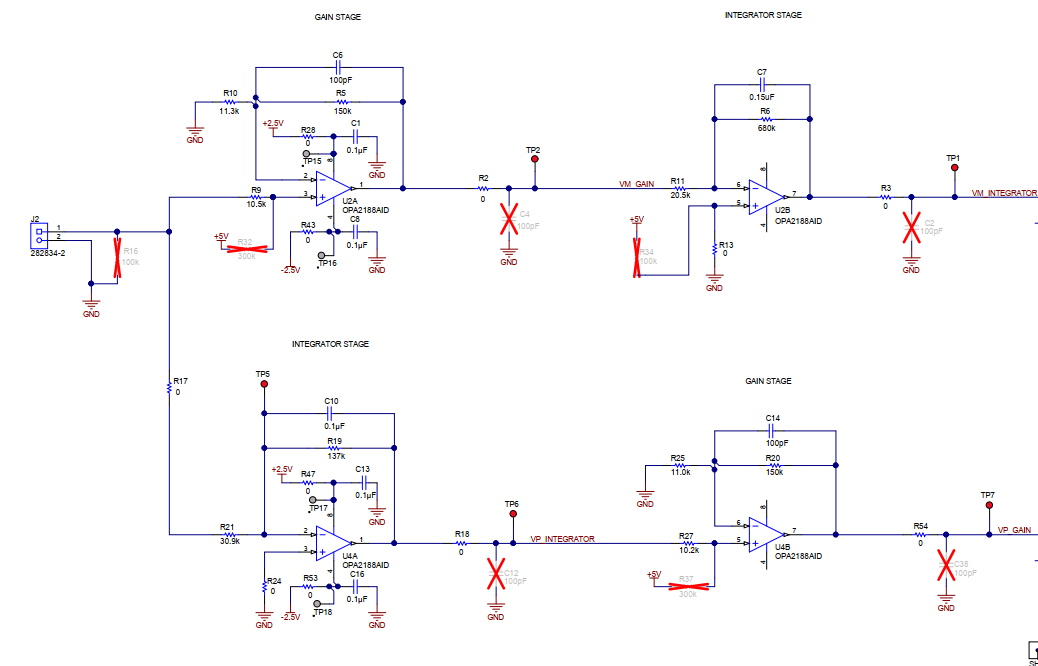
2. Instead of using a digital integrator I have tried to use an analog integrator (similar to TIDA-00777) but the waveform I get is very noisy as shown below, is there any method to reduce the noise?

Frequency - 200Hz, Current - 24A (RMS) ----- Yellow- output of the analog integrator || Orgage- is the FFT of the output

  • Hi, thanks for the questions, let me look into these ad get back to you as soon as possible.

    -Brian

  • Hi  Virinchi,

    For the first question, it looks like these values are calculated based on the Rogowski coil itself and the equations explained in section 4.1.3. Can you share more information on the Rogowski coil used in your testing?

    For the second question, the TIDA-00777 is designed for 50Hz line frequency and it looks like you are running at 200Hz. The R and C integrator values should be tuned based off the methods shown in 3.3.2 and 3.3.2 of the TIDA-00777 design guide. Also, your scope will need to be in bandwidth limit mode and please be cognizant that the ADC used for sampling needs to capture signal up to certain bandwidth based on the ADC sampling rate.

    -Brian 

  • Hi Brian,

    Thanks for responding.

    1. I'm using the same Rogowski coil (TIDA-01063) PCB photo attached below, and have measured the resistance from the bode100 impedance analyzer and resistance is around 12-15 ohms.

    Even with the calculations: I'm getting 12.49 ohms. Can you please let me know about the capacitance calculation also?

    2. I have reduced my sampling rate of the oscilloscope to 1MSPS and captured the waveform at 50Hz.(attached below)

    Yellow -PCB Rogowski coil 

    Green - lab current sensor (for reference purpose)

  • Hi Virinchi,

    For the parameters, the designers verified the self inductance using inductance analyzer and used used peak observed value out of 10 PCB coil sensor for doing step response simulation to get worst case delay, etc. I am not sure why there is such a large variance from what you are seeing, but it is good that your calculation values are atleast approximately what you are seeing through the analyzer. 

    For the noise in your waveform, probes or any other load can cause distortion in the waveform. Do you have any additional load on the Rogowski coil? 

  • Hi Brian,

    I haven't connected any load to the except the damping resistor 580 ohms. But can you also let me know about the capacitance calculation?

    Thank you, 

    virinchi

  • Hi Virinchi,

    The total capacitance in this case was measured using the first resonant frequency and leveraging the equation: C = 1 / (4π2 f2 L)   Capacitance [F], where the resonant frequency is f and the inductance is L.

    -Brian