This thread has been locked.

If you have a related question, please click the "Ask a related question" button in the top right corner. The newly created question will be automatically linked to this question.

TIDA-01525: same request(For the higher voltage with TIDA-01525)

Part Number: TIDA-01525
Other Parts Discussed in Thread: DAC80508

Hi TI,

I have the same request.

The current range of TIDA-01525 is satisfactory, but I want to apply PVDD at least 15V (because the voltage of the load is high)
Can you give me a guide design or suggestion for this part?

rgds,

  • Hi Junghoo,

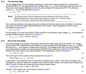
    Take a look at the calculations section of the TIDA:

    With a PVDD of 15V, you'll need an op amp with an input range of up to 14.5V if all resistor values are kept the same. This is based off of the voltage drop on R2. Alternatively, you can increase the resistors by a factor of 10 to lower the required input voltage on A2 to ~10V. This design choice will be up to you and then you can pick a suitable op amp.

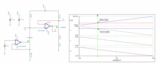
    You can also increase the DAC output voltage to lower the input range of A2. I've attached a simulation so that you can test different values that you may want to use in your final design. You can look at the required V+ input range of A2 and choose an appropriate op amp.

     TIDA-01525.TSC

    Best,

    Katlynne Jones

  • Dear Jones,

    Thanks for your quick and kind reply.
    Here are some additional questions that are more detailed.
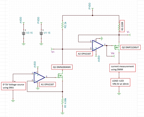
    The picture is a circuit modified from your simulation, and I actually did the same test as the picture.
    When VC is 5V, IOUT is about 10mA, almost similar to the calculation.
    In VC 2.4~5V section, IOUT looks linear.
    By the way, at VC 0~2.3V, the current is fixed about 4~5mA or more.
    That is, the minimum current in the circuit is at least 4mA.
    A minimum current of about 4mA is my error? Or is it a limitation of the circuit?

    One of the big reasons why the TIDA-01525 is an attractive solution to me is its low minimum current.
    To clarify my goals,
    Multiple high-side constant current sources with IOUT=0.1~10mA / Compliance V = 12~13V using DAC80508.
    The maximum current is enough at 10mA, but the lower the minimum current, the better.
    Is there any way to transform TIDA-01525? Or is there another design or help that suits my purpose? Like the TIDA-01525.
    For reference, I also referred to the following documents, and there was no significant difference in the results.

    "SLYT768 - High-side current sources for industrial applications"
    "SLAA867 - Programmable, two-stage, high-side current source circuit"

  • Hi Junghoo,

    The minimum current is caused by the voltage at the top of R1 being non zero when the DAC output is 0. This is probably due to the transistor. This causes current though R1 that is amplified by the current mirror. Also keep in mind that we are modeling a DAC with an ideal voltage source. The DAC output will have a few mV of error at code zero (due to its output buffer), and so will the op amps chosen. In any case, it is hard to get a true 0V output using unipolar supplies. 

    You can take a look at these two circuits to see if they might work for you:

    Smart DAC LED Biasing Circuit with Low-Power Sleep Mode (Rev. A)

    High-Side Current Source LED Biasing Circuit Using Smart DACs

    Best,

    Katlynne Jones

  • Hi Katlynne,

    I really appreciate!

    I understood your comment. I guess that maybe for my goal it would be better to use the differential amplification of the howland current pump than the current mirror. I would also like to get advice on this part, but I will use an appropriate post after judging that it is out of the posted topic "TIDA-01525".
    Thanks again for your help.

  • Hi Junghoo,

    Thank you for your response. I'll close this thread for now, but you can re-open it by replying if you have any related questions.

    Best,

    Katlynne Jones