This thread has been locked.

If you have a related question, please click the "Ask a related question" button in the top right corner. The newly created question will be automatically linked to this question.

TIDA-00489: PIR Amplifier Stability Analysis

Part Number: TIDA-00489
Other Parts Discussed in Thread: LPV802

Hello.

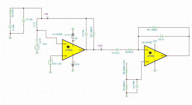
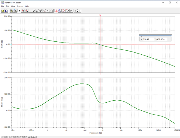
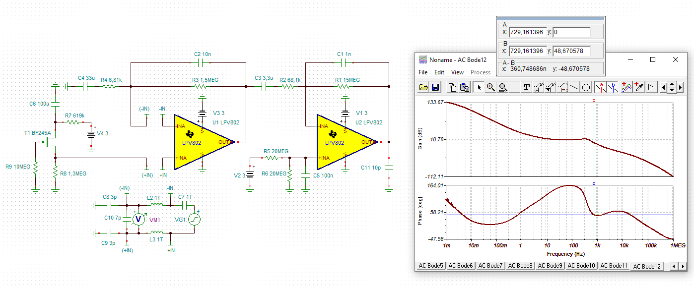
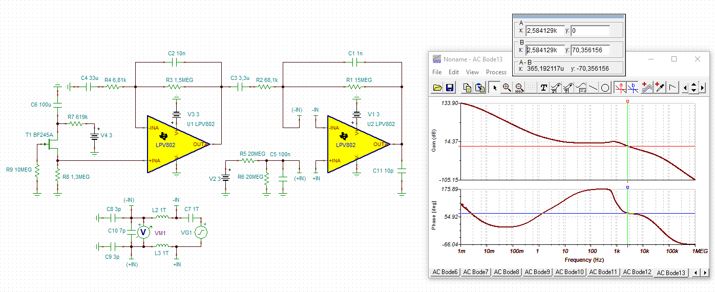
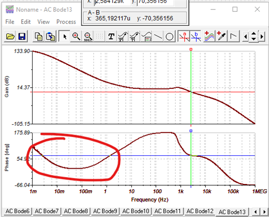
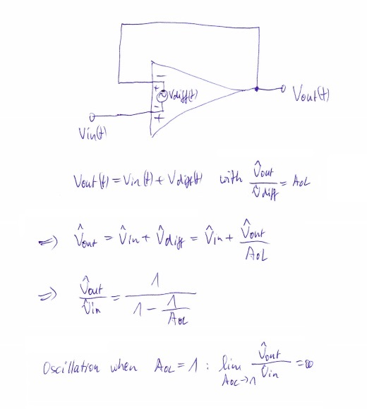
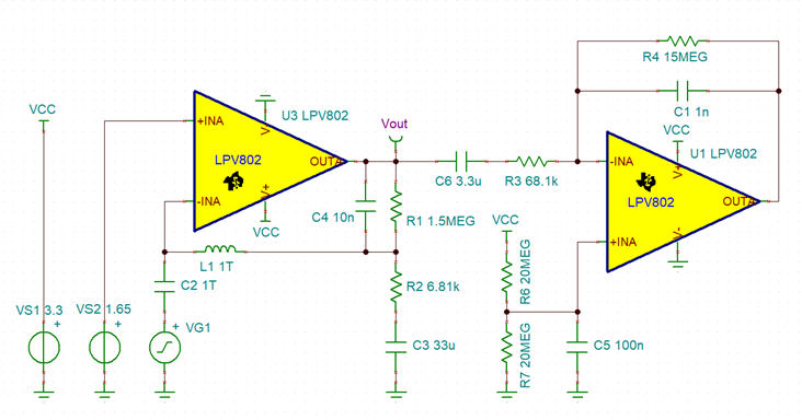
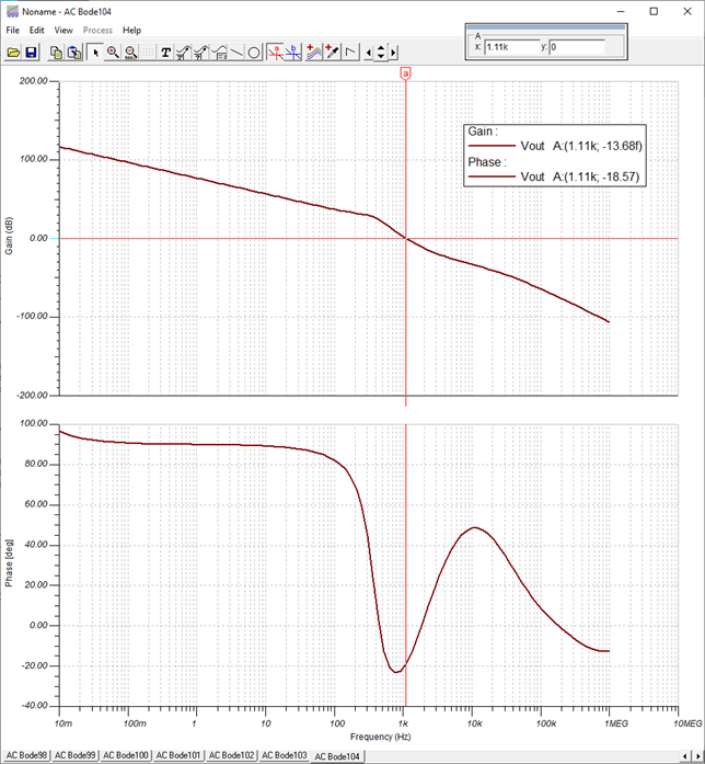
I'm attempting to measure the phase margin of a TI reference design (TIDA-00489) using the method outlined in https://training.ti.com/ti-precision-labs-op-amps-stability-spice-simulation?context=1139747-1139745-14685-1138805-13850. According to this simulation, if I'm doing it correctly, the first gain stage of the amplifier chain appears to be unstable. I can't imagine this to be the case with a reference design, so I must assume I am performing the analysis incorrectly. Can someone validate or correct my method?

Thanks.

  • Hi Nick,

    I have reviewed your schematic and believe you are probing loaded AOL. To get the correct analysis result, you should be probing the junction of L1, C4, R1, and R2.

    We reproduced the simulation on our side and see approximately 50 degrees of phase margin at this point.

    Please let me know if there are any additional questions.

    Best,

    Steven 

  • Steven, thanks for the response.

    Your answer seems contrary to the answer that I received in the related question, where I was instructed to probe at the output of the op amp: https://e2e.ti.com/support/amplifiers-group/amplifiers/f/amplifiers-forum/1082473/tlv8541-tina-ti-stability-simulation

    Can you please explain why these two circuits should be probed at different points in the circuit?

    Thank you.

  • Nick,

    I've reviewed the previous post you referenced in your last reply.  I'm assuming the instructed probe point you mentioned is from the training video you referenced in your previous post as I did not see any probe point instructions from the poster.? If so, referring to the training video, if you notice those circuits are breaking the feedback loop at the output of the opamp.  The point where you are breaking the loop in this post is at the input of the opamp.

    For this post, the transfer function from Vout to your ac input is that of the opamp only which is not loop gain.  Loop gain in both cases will be the circuit side of the loop break inductor (output) to the junction of the loop break inductor and injection capacitor (input).

    Referring to Steven's circuit and relating the terminology to the training video, AOL = Vout, Vout/Vfb = 1/Beta, Vfb = AOL*Beta which is your loop gain and phase.

    Regards,

    David

  • Thank you, understood. I have a couple follow up questions.

    1. Does this mean that the circuit in the related question was probed and measured incorrectly?

    2. How would one go about performing the same measurement for the 2nd gain stage of the above circuit?

    Thanks.

  • Nick,

    1.  Yes, Vout is looking at AOL for that circuit also.

    2.  The second stage can be simulated the same as the first.  Since its an inverting stage, I would likely choose to break the loop at the output of the opamp, but you should see similar results if you break the feedback at the negative input.  The first stage can be ommitted from that simulation as it will not have an impact on the result.  Because C3 will block DC, the input side of C3 can either be set to 1.65V or 0V as it will not change the DC bias point of the opamp.

    Regards,

    David

  • Hi Nick,

    I would do the phase stability analysis by including the JFET circuit of the PIR sensor and its output impdance and by including the input capacitances of the following comparators:

    nick_lpv802.TSC

    As you can see I get the same result as David.

    And the second LPV802 shows a phase margin of 70°:

    nick_lpv802_1.TSC

    Kai

  • Thanks, all, for your input.

    Kai, thanks for hopping in.

    1. Could this dip circled here indicate instability in extremely low frequencies, or do we truly only care about the loop phase at unity gain? Intuitively, wouldn't any positive gain with poor phase margin be of concern?

    2. What if that dip reached 0deg, or even went negative?

    Thanks.

  • Hi Nick,

    to simplify the calculation see this simple voltage follower circuit. Think of the input and output voltage signals Vx(t) of sine waves all having the same frequency. The phase shift between Vdiff(t) and Vout(t) internally of OPAmp shall be such that we can write:

    From this you can see that the phase shift is only relevant at and arround AOL = 1 = 0dB.

    Kai