Other Parts Discussed in Thread: LM5156H, CSD19531Q5A, CSD19534Q5A
Dear All,
we are designing similar flyback based on PMP22764 with LM5156H IC.
I this e2e thread is stated that the PMP22764 was designed for best efficiency, but we would like to have better so i did a calculation with CSD19531Q5A ( currently used on PMP22764) and CSD19534Q5A and i get approx. 1W difference, please can you look at may calculation if i'm missing something? Also i used Schottky diode on the other side STPS10200SF .
Transformer: ZB1368-AL Coilcraft
Vout= 55.75V
Iout_max = 1.2A
Vin from 18V to 30V -> Typ 24V

My calculation
| Vcc | 10 | V | External from Transformer Aux Winding | CSD19531Q5A | |||||
| Isource | 1.65 | A | Figure 8-14 Peak Driver Current vs VCC | Qg | 37 | nC | |||
| Isink | 1.75 | A | Figure 8-14 Peak Driver Current vs VCC | Rdson | 5.3 | mOhm | |||
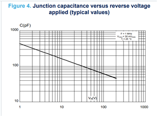
| Coss | 560 | pF | |||||||
| Idriver | 1.7 | A | |||||||
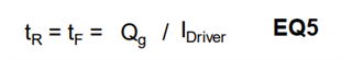
| tr | 22.42424242 | ns | Rise time | EQ5 | |||||
| f_sw | 252.5 | kHz | tf | 21.14285714 | ns | Fall time | EQ5 | ||
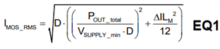
| I_rms | 4.85 | A | EQ 1 | ||||||
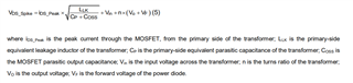
| V_ds | 58.2 | V | EQ 2 | Rdson_factor | 1.75 | ||||
| I_peak | 7.56 | A | From the SNVC240 calculator | ||||||
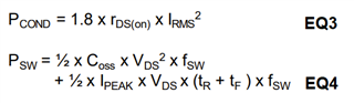
| P_cond | 0.218171188 | W | EQ3 | ||||||
| P_sw | 2.659586246 | W | EQ4 | ||||||
| P_tot | 2.877757434 | W | |||||||
| Vcc | 10 | V | External from Transformer Aux Winding | CSD19534Q5A | |||||
| Isource | 1.65 | A | Figure 8-14 Peak Driver Current vs VCC | Qg | 17 | nC | |||
| Isink | 1.75 | A | Figure 8-14 Peak Driver Current vs VCC | Rdson | 12.6 | mOhm | |||
| Coss | 257 | pF | |||||||
| Idriver | 1.7 | A | |||||||
| tr | 10.3030303 | ns | Rise time | EQ5 | |||||
| f_sw | 252.5 | kHz | tf | 9.714285714 | ns | Fall time | EQ5 | ||
| I_rms | 4.85 | A | EQ 1 | ||||||
| V_ds | 58.2 | V | EQ 2 | Rdson_factor | 1.75 | ||||
| I_peak | 7.56 | A | From the SNVC240 calculator | ||||||
| P_cond | 0.518671125 | W | EQ3 | ||||||
| P_sw | 1.221844923 | W | EQ4 | ||||||
| P_tot | 1.740516048 | W |
Would you suggest CSD19534Q5A over CSD19531Q5A , or i'm missing something in the above calculation?
Br,
David.