This thread has been locked.

If you have a related question, please click the "Ask a related question" button in the top right corner. The newly created question will be automatically linked to this question.

PMP22764: Input & Output Capacitor and Filter

Part Number: PMP22764
Other Parts Discussed in Thread: LM5156H

Hi All,

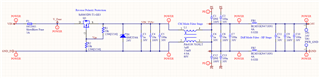
we are designing a similar flyback converter to PMP22764 with LM5156H and have some questions.

1) Input Capacitor selection and calculation on PMP22764

when we use SNVA866 EQ23 to calculate Cin_min for PMP22764 with ripple 100mV we get ~ 60uF

On PMP22764 there are 4x 10uF,50V,X7R,1210 (C7,C8,C9,C10) ant 24V this is approx. 4x5uF = 20uF and in combination with C5 ( 47uF) = ~ 67uF is this the correct way to calculate the input capacitor?

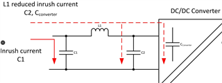
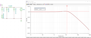
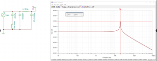
2)Input filter estimation for conducted EMI from flyback converter to input

There are multiple app notes from TI on this subject but all are regarding to a BUCK and not a FLYBACK converter ( SLUP362, SNVA489C,  SNVU693, SLYT782, SNVA810 ...)

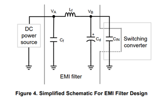
So in PPMP22764 the L1 is Lf, and we are assuming that Cf is C5 but then the Cd is missing, please can you explain how dis you estimate or calculate this filter for the PMP22764?

3) Output Capacitor selection and calculation on PMP22764

The PMP22764 uses only 56uF.

But when i use EQ 21 and 22 from SNVA866 i get:

NP =1, Ns =2, Vload=56V, D' = 0.4 @Vin=18V, Lm=15uH

fz_rhp ~ 30kHz

fcross = 30/5 = 6kHz

dVload = 100mV, dIload= 1.25A/2 = 0.625A

Cload_min= 165uF 

Can you comment why only 56uF is used, this is 3x less than Cload_min ?

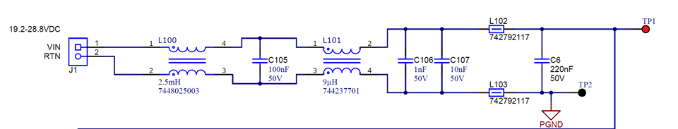
4)  How is the L2 PI output filter designed, what are the assumptions?

Best Regards,

David.

  • Hi David,

    I am looping in the original designer to comment in more detail. But for now.

    1. Your assumption are correct

    2. Cd are the 4 ceramic caps after L1, you can lump them together as one cap. The filter is just an estimate and will need to be tuned for your system (Source, load, other items on the input line, etc).

    3. The designer probably specified the output cap for a given ripple voltage, not the transient load. If you have transients, then the equation you used might be better.

    4. The flyback converter has a lot of ripple current on the output, so you need ceramic capacitors to handle that. But if you only use ceramics, the output voltage ripple will be too high. So the LC filter is used to keep the excessive ripple current out of the electrolytic cap and keep the output voltage ripple down.

    Thanks,

    Robert 

  • 1)  The 60uF calculated for 100mV of ripple assumes 0 ohms ESR for the capacitor.  The flyback has large peak input current that will also generate a voltage across the capacitor ESR and add to the total ripple voltage (although the capacitor ripple and ESR ripple are not in phase).  The PI filter is usually more cost effective and smaller than using only capacitors.  C5 provides filtering with L1 and also lowers the line impedance.

    2)  Yes, Cd is C7-10 ceramic caps.  The L1/C7-10 LC filter will have high Q without damping, so keep L1 relatively small (<10uH?).  C7-10 are selected to handle the high frequency ripple current and provide a "reasonable" voltage ripple.  L1/C5 is then calculated to achieve the desired voltage ripple.  3.3uH will typically keep the Q low enough to work without a damping capacitor.  A damping capacitor can be placed in parallel with C7-10, but make sure the ripple current rating is not exceeded.  Multiple aluminum capacitors may be required.  A polymer or hybrid polymer will have a higher ripple current rating so fewer will be required.

    3)  The test report for PMP22764 shows a -287mV transient with a 625mA to 1.25A load step.  The measured loop bandwidth is about 5kHz.  Your capacitance calculation for a load step is specified at -100mV for a 6kHz bandwidth.  Dividing the 165uF by 2.87 (287mV/100mV) results in 57.5uF.  The 2.2uF ceramic capacitors will also add to the bulk load capacitance.  So, the equation is correct; PMP22764 just has a larger load step response.

    4)  Yes, agree with above response.  Similar to the input PI filter, the ceramic capacitors are selected to handle the ripple current and provide "reasonable" ripple voltage.  The bulk cap is then calculated to provide the desired load step response.  The inductor can then be selected to provide the desired high frequency ripple voltage.  With peak current mode control the output PI filter results in three frequencies of interest in the power stage.  There is a pole at the total output capacitance and RLOAD.  There is a zero at the ESR of the output bulk cap.  There is also an LC resonance resulting from the output inductor and the ceramic capacitance to the left of the inductor, C2/C3/C13/C14.  Again, without any damping capacitor in parallel with the ceramic capacitors C2/C3C13/C14, the Q of this LC resonance can be high.  It is best to keep the inductor below 1uH so the LC resonance is high enough in frequency so as not to effect the control loop.  Again, damping capacitance can be added, but has to be ale to handle the high RMS current.  Multiple aluminum capacitors will be needed or a polymer/hybrid.

    It is usually necessary to add common mode inductor(s) on the input to pass EMI.  Below is a typical EMI filter that I added to the PMP22764 design.  It has not been tested, but is based on similar designs.

    Thanks,

    David

  • Hi David,

    Thank you for the reply. Do you maybe know app notes where all above statements that you make are described? Or do you know a book that covers this topic ( input output caps and input output filters) for peak current mode control flyback?
    1) Large peak input current in flyback
    a) do you mean the inrush current? 
    b) can this be handled without use of a Soft-Start circuit and how?
    c) in case of PMP22764 does the L1 reduce the inrush current? But doesn't this mean that the inrush current will go through the ESR of capacitor C5?
    A more common solution is to add an inductor to limit the inrush current. This has the added advantage of acting as an input filter and reducing conducted EMI interference when used as a Pi-Filter. The inrush current is split between the supply voltage capacitor, C1, and the inductor-limited input current required by C2 and the converter (shown dotted).
    2) Input filter:
    -> the LC filter L1(3.3uH) - C5(47uF) is the filter that filters the conducted EMI from the converter to the DC input. Is that correct? The PMP22764 filter uses an electrolytic capacitor for C5 and if we assume that the C5 has 500mOhm ESR ( for better understanding) then this filter has a low Q close to 1 and a cut-off frequency of 12.75kHz. Is that correct?
     In order that the filter doesn't mess-up the stability of the converter the Output impedance of LC filter  L1(3.3uH) - C7toC10 (4x 10uF ~ 20uF @ 24V) must be lower that the input impedance of the converter.
    So the converter is switching at 250kHz and has efficiency around 90% can i estimate the input impedance of the converter like:
    Zin = ( Vin^2 * n ) / (Pout) = (24^2 * 0.9) / (56 * 1.25) = 7.5Ohm and then choose the Zout of the LC (L1 - C7toC10) filter to be 0.75Ohm max ?
    And the LC (L1-C5) cut-off frequency to be 1 decade below the 250kHz fsw -> f_filt -> below 25kHz ? Is this a good starting point?
    In PMP22764 f_filt is 12.75kHz and Zout_filt = 0.4Ohm approx. ?
    The simulation shows high Q for the L1 C7toC10 filter:
    if use following equation for Q = (1 / ESR) * SQRT (L/C)  and assume ESR 1mOhm 
    Q= (1/0.001)*SQRT(3.3/20) ~ 406
    How high should be the resonance of L1-C7toC10  in order not to interact with converter stability?
    Can this high Q cause over-voltage or affect the stability regardless that the Zout of the filter is low ? Do you suggest adding a damping cap on the right side of the L1 eg 1x 470uF electrolytic capacitor?
    How can I estimate the ripple current of the flyback and then compare this to the datasheet value ? (Converter is switching at 250kHz , and the Ds of cap only states ripple current at 100Hz)
    3) ok
    4)
    Ok now I understand the bulk cap is calculated for the step load response, but can you tell how to estimate (or calculate) the ceramic capacitance ( C2,C3, C13, C14 and C4, C15) regarding to the desired current and voltage ripple ?
    And how is the L selected ( calculated) regarding this , are there some application notes or equations?
    if the control loop frequency is 5kHz, what factor should be LC filter cut off frequency in order not to interact with the control loop? 
    If i look at the PMP22764 and i calculate the f-filter = 1/2*pi*SQRT(LC) ~ 139kHz (330nH, and effective 4uF @ 56V), this is factor of 28 , is my calculation right?
    5) Yes I agree that additional CMC and FB will be needed.
    Why do you use the big CMC L100 ?
    Here is my input filter that I use for EMI, what do you think ? 
    Best Regards,
    David.
  • A good starting point for information is the Texas Instruments Power Supply Design Seminars.  The papers and presentations are archived at the link below.

    https://www.ti.com/design-resources/seminars/power-supply-design-seminar-psds/psds-resources.html

    On the first page, the 2016 seminar topic "Switch-mode power conversion compensation made easy" is a good source for control loop design.  Click the "2008 to 2000" link at the top and scroll down to 2002.  The topic "Achieving high-efficiency with a multi-output flyback supply using self-driven synchronous rectifiers" has information on designing the input and output filters.

    1)  The in-rush current is limited by the soft-start.  L1 is used to filter the high frequency switching current.  It would take a very large inductance to have any affect on the in-rush current.  The in-rush turn-on time for an isolated converter is typically 5-100 milliseconds.

    2)  Usually if the output impedance of the input filter is a factor of 10 less than the input impedance of the converter there will be no interaction with the control loop.  If there is interaction, you will be able to see it in the Bode plot as a resonance at the filter corner frequency, in this case 12.75kHz.  The Bode plot in the test report shows no resonance at this frequency. 

    Our Power Stage Designer Tool can be used to view the power waveforms of most converter topologies.  You input the converter parameters and can then view waveforms of the power components.  There are also tools available in the drop down tabs for various calculations.

    https://www.ti.com/tool/POWERSTAGE-DESIGNER?keyMatch=POWER%20STAGE%20DESIGNER%20TOOL

    3)

    4)  The Power Stage Designer Tool will show the current through the input and output capacitors.  From this you can calculate the capacitance and ESR required for the desired input or output ripple.

    5)  For EMI, you really need to measure a baseline of the emissions then design a filter for the needed attenuation.  The ferrite beads and low value CM inductor usually provide enough attenuation at frequencies above 5-10MHz, depending on the corner frequency of the filter.  Below 5 MHz you will mostly have the switching frequency and its harmonics to attenuate.  The DM mode PI filter C5/L1/C7-10 provides most of this attenuation.  Depending on the impedance of the stray coupling paths, the larger L100 CM inductor is sometimes needed to attenuate the emissions below 5MHz to the desired level.