This thread has been locked.

If you have a related question, please click the "Ask a related question" button in the top right corner. The newly created question will be automatically linked to this question.

TIDA-00281: MOSFET failure

Part Number: TIDA-00281
Other Parts Discussed in Thread: CSD19535KTT

Hi Team, seeking for some assistance

Used TIDA-00281 reference design for my BLDC motor. in this schematic i have used LDO instead of buck regulator. 

when i start BLDC motor with 48VDC supply. we gradually increase duty cycle from 10% - 80% and 80% - 10% the motor is run fine in CW and ACW direction. in this test condition i didn't sense phase current. 

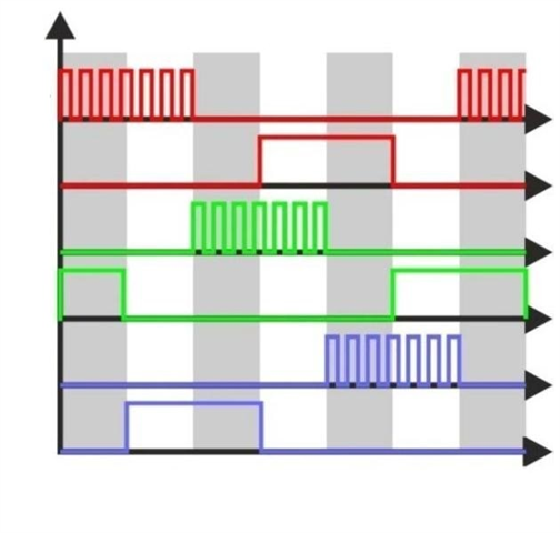
here, i have attached PWM waveform. 

After some time suddenly motor stop running and MOSFET was damaged also my gate driver IC (phase-C) damaged.   

/resized-image/__size/640x480/__key/communityserver-discussions-components-files/234/2061.MicrosoftTeams_2D00_image-_2800_1_2900_.png

Thank you

-Mark

  • Mark,

    I have forwarded your question to our Automotive system team experts to look into.

    Regards,

    Martin Staebler

  • Hi Mark,

    The attached image of PWM pattern for the high and low side MOSFETs is only indicating that you are using Unipolar Independent PWM technique for the BLDC Motor control. Regarding the MOSFET failure, it is important to use the right dead time setting as mentioned in the section 7.7 of the user guide of TIDA-00281. While doing the dead time setting, also consider the rise/fall time of the MOSFET and the gate resistor (Rg) value used in your schematic or during the testing. In the datasheet of MOSFET CSD19535KTT, rise/fall time is mentioned for Rg = 0 Ω, therefore if you are using the different value of Rg (i.e. 10 Ω) then rise/fall would be different in that case. I can not find the information in your question that which MOSFET (which phase and high or low side) was failed. Another possible reason of MOSFET failure could be destructive Avalanche failure , it happens when Avalanche energy is larger than the specified Avalanche energy limit in the datasheet (i.e. 451 mJ for the MOSFET CSD19535KTT). Many times suboptimal PCB layout can cause more parasitic which results to destructive Avalanche failure. Since you are using the Unipolar Independent PWM technique, switching and conduction losses will be asymmetrical in high and low side MOSFETs. I hope that you have made proper heat sink arrangement while testing. In case of continuously running the Motor for long time during testing while varying the duty cycle, MOSFETs temperature will rise continuously. With increasing temperature, Rds-on of the MOSFET will increase further and cause even higher conduction loss to further accelerate the temperature rise. Therefore in to run the Motor continuously for long time during testing, having proper heat sink arrangement is important. A MOSFET can be damaged if the gate voltage will exceed the specified limit in the datasheet even for a very short instant. Since you have mentioned that phase C gate driver was also damaged, there is possibility of dv/dt failure. In such failures, due to high transient spike in voltage, drain of the MOSFET gets coupled to gate of the MOSFET through internal gate capacitance. It causes high voltage rise at gate of the MOSFET and if it is more than the specified gate voltage limit then in such cases MOSFET failure occurs. Just for the information regarding the used Unipolar Independent PWM pattern from my past experiences, although using Unipolar Independent PWM technique results in lower switching/conduction losses and low ripple in DC link capacitor but it in not an optimal PWM technique for Motor control due to difficulty in current sensing. Therefore in industries many times Unipolar complementary PWM technique is more preferred as compare to Unipolar Independent. 

    Best Regards,
    Prashant Kumar