This thread has been locked.

If you have a related question, please click the "Ask a related question" button in the top right corner. The newly created question will be automatically linked to this question.

TIDA-080004: TMS320F28023 has no SPI response signal

Part Number: TIDA-080004
Other Parts Discussed in Thread: TMS320F28023,

Hi Team,

I ask this from our customer.

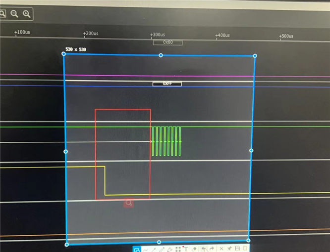
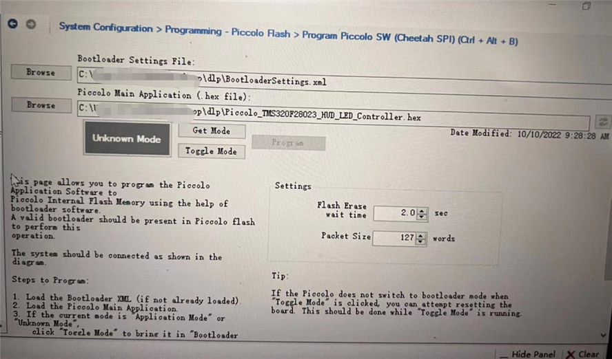
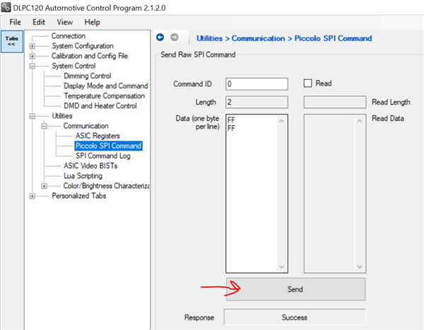
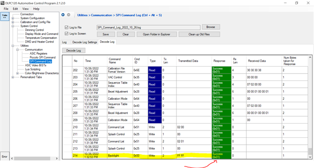
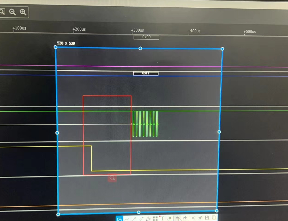
Customer is testing the TIDM-080004, by controlling the S9KEAZ128AMLHf, using SPI signal to send commands to TMS320F28023, such as backlight adjustment. The control result is that the brightness of the projection light can be adjusted, but customer found that the TMS320F28023 has no SPI response signal output after they capturing the signal through the logic analyzer. Could you please help analyze the reason for this? Thanks!

BR

Julia

  • Hi Julia,

    Does the customer have access to the following SPI documentation guides?

    DLPU061_Piccolo_SW_Guide_201803.pdf

    DLPU057_Piccolo_SPI_Command_Guide_201803.pdf

    In the SPI command guide it should have examples of commands and responses like this.

    Thanks,

    Alex Chan

  • Hi Alex,

    Customer have tested the TIDA-080004 code and they found F28023's output is different.

    According to https://www.ti.com/lit/ug/dlpu057a/dlpu057a.pdf , in the case of the figure below, F28023 SPISOMI output should be 0xFF........0xFF, 0x01. But SPISOMI in the waveform captured by the customer is 0xFF........0xFF, 0xFF. You can also see this in following attached video. SPISIMO's signal is the same as following picture's Host(Master), SPISOMI's signal is not the same as following picture's Piccolo(Slave).

    It seems that Piccolo missed the "Response Byte" 0x10, but I can't find any explanation about this response bit, when is it generated and what could be the reason for missing it?

    For your reference,customer now are using software simulate spi, and it may cause a delay between SPICLK(green) and SPI_ENABLE(yellow).

    And customer's code is programmed from flash memory.

    Could you please help analyze the reason for this? Thanks!

    BR

    Julia

  • Hi Julia,

    I am looking into this. Did the customer build their own board or do they have our EVM or electronics boards?

    One thing that can be tried is in the DLPC120 Control Program under utilities there is Piccolo SPI command and then a SPI command log. If the customer purchased our EVM or can hook up and communicate with the DLPC120 Control Program with their system they can do this check.

    The example below was sending a backlight value of 65535.

    Then in the SPI command log tab you can decode and see the response. In this case I see a Success and got a 0x01 as a response.

    Thanks,

    Alex Chan

  • Hi Alex,

    Customer use TI EVM now. Customer can send commands through the DLPC120 Control Program to realize backlight adjustment, and there is a response signal on C2000. However, customer think that this can only prove that the C2000's SPI is working, which does not solve the problem that the customer simulates SPI through software without a response signal. Customer is using IO to simulate SPI, not using hardware SPI.

    So customer want to know why SPI have no response signal when using SW simulate SPI. Should a delay between SPICLK(green) and SPI_ENABLE(yellow) will cause it? 

    BR

    Julia

  • Hi Julia,

    What is the SPI clock speed the customer is using please see in the datasheet based on clock phase there are certain SPI clock rate limits.

    Could the customer try another command please see the following example from the Piccolo SPI Command User Guide.

    I am noticing that in the initial command description for a backlight value write which is the following. There is no response information.

    However there is a read response information. 

    Please also see example and see if customer can try it out and see what shows up.

    Thanks,

    Alex Chan