This thread has been locked.

If you have a related question, please click the "Ask a related question" button in the top right corner. The newly created question will be automatically linked to this question.

TIDA-00828: Target and Sensor Design

Part Number: TIDA-00828
Other Parts Discussed in Thread: LDC0851, LDC0851EVM, LDC1312

Hello Team,

  we are developing inductive encoder  using reference design of  TIDA-00828., while referring all reference documents I found all documents related to sensor design . but PCB layout and Gerber file of target design is not present. can you share design files related to target design for 32 position.

Regards,

Sayali 

  • Hello Team,

      One more thing for sensor design it is recommended that use trapezoidal form coil, but while using below online tool for designing sensor coil for LDC0851 it shows only circular pattern and not trapezoidal.

    https://webench.ti.com/wb5/LDC/#/spirals

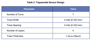
     while in 32 position example trapezoidal coil design is used.

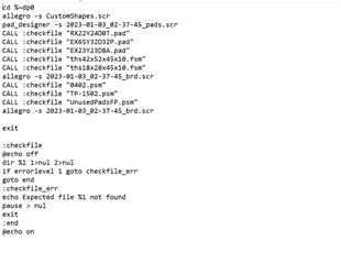
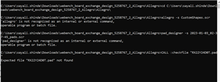
    Just to check how coil design is imported , I tried with some value and exported board layout with Cadence Allegro 16.0-16.5 option. As per read me instruction is downloaded file when I clicked on bat bat it show some error.  to eliminate error I need to put correct location. can u help us which exact location we need to put and where in bat file. For reference I am attaching snapshot of bat file.

    Regards,

    Sayali

  • Sayali,

    I don't think we have the gerbers for the trapezoidal coils in TIDA-00828, but I will check our archives to confirm.

    As for your updated comments, could you give some more details about what you are doing? Are you trying to import a coil from the online tool, or another PCB with a coil?

    Regards,
    John

  • Hello John,

          Yes I am importing coil from below online tool for LDC0851.

    https://webench.ti.com/wb5/LDC/#/spirals

    with this I am facing 2 issue.

    1. as per recommendation by TI we need to use trapezoidal coil and not circular but in above online tool for LDC0851 it shows only circular option.

    2. After importing design files for circular option, it contain bat file. but while running that running that bat file it gives error. (below snapshot)

      As per read me instruction text file , it tells to give proper location in bat file. can you suggest which and where to give location.

    Regards,

    Sayali

  • Sayali,

    The online tool coil design tool will provide only a circular spiral coil design for theLDC0851.
    It will provide circular, square, hexagonal and octagonal coils for other inductive sensing devices.

    The Excel-based Inductive Sensing Design Calculator Tool will provide racetrack and circular spiral coils.

    I will try to reproduce your findings and will update this thread tomorrow.

    Regards,
    John

  • Hello John,

      thank you for reply.

    I have a query related to sensor design of (TIDA-00828 -Inductive Sensing 32-Position Encoder Knob Reference Design using the LDC0851)

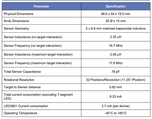
    As per key specifications and sensor design in design guide (snapshot below) the inductance is 2.32uH and sensor frequency is 17.6MHz frequecny.

    when I put this value (no. of layer, OD,ID,capacitance )in LDC_Tools-ext51 excel the sensor inductance doesn't give 2.32uH value and even shows error of high sensor frequency.

    please guide how to co relate design guide value with excel. for reference I have excel sheet. And even if we want to change coil pattern from trapezoidal to circular which value we need to consider first inductance i.e 2.32uH or OD of required circle.

    LDC_Tools-ext51.xlsx

    Regards,

    Sayali

  • Hello John,

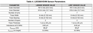
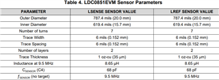
        for LDC0851EVM also the sensor parameters doesn't not match with spiral inductor desing. If I put OD-20mm,no of layers-2, no of turns-7 and trace width and spacing 6mils, capacitor 64pF I should get inductance value as 8.65 and freq as 9.5Mhz but it give inductance value as 4.84uH and frequency 12Mhz.

    please tell where is the mistake in considering value or using the tool.

    Regards,

    Sayali

  • Sayali,

    Just to confirm my understanding of your former question: do you wish to relate the design a spiral inductor that is equivalent to the design guide's trapezoidal inductor? 

    Referring to your most recent question, I arrived at the same results you reported. I don't know what exact conditions led to the results in Table 4.
    I will investigate this further and update this thread tomorrow.

    Reards,
    John

  • Hello John,

      yes your understanding is correct, I want to co relate the design a spiral inductor that is equivalent to the design guide's trapezoidal inductor.

    if that value matches then it is easier to understand the calculation and equations. please clarify the doubt asap coz this we cannot proceed for PCB design.

    Let me know if you require any more details from our side.

    Regards,

    Sayali

  • Sayali,

    I have been unable to duplicate the EVM results using the tool, so no success yet.
    I will update this thread on Monday.

    Regards,
    John

  • Hello John,

         I think there is confusion , which EVM you are considering ? I want to validate theoretical calculation of spiral inductor design(excel based tool ) with values mentioned in user guide . e.g I want to understand how the below values (inductance 8.65uH , capacitance 68pF assuming no of layers 4 and OD-20mm) has been derive. when I put input values i.e no of layers 4, OD 20mm, sensor capacitance  68pf in spiral inductor design excel tool, the value for sensor inductance come as 4.846uH. I want to know why these sensor inductance value does not match with user guide of LDC0851EM. Am missing some calculation? 

    6237.LDC_Tools-ext51.xlsx

    Regards,

    Sayali

  • Sayali,

    For trouble-shooting purposes, I entered the parameters from Table 4 (from the LDC0851 EVM User's Guide)  in the spreadsheet sensor design tool.
    That spreadsheet is attached.

    For 2 layers, 7 turns/layer, the latest version of the tool (attached) reports 5.351uH with no target, and an operating frequency of 11.47MHz with a 68pF cap.
    Figure 2 in the EVM user's guide reports 6.2uH for the 2-layer sensor or reference coil, which is closer to my reported value than to the one in Table 4 (=8.65uH). The author of the app note is no longer with TI, so the background on the two different values reported in the EVM user's guide (6.2uH ≠ 8.65uH) is not available. 

    The difference between my calculated value (=5.351uH) versus the lower of the two reported sensor inductances in the EVM user's guide may be due to tool updates that were done after the app note was released (2015) and revised (2017). 

    There may be an issue with the spreadsheet you attached in your last reply. It had the Sensor Shape set to Circular, but the field Long Side of the Inductor set to 8mm, which should not differ from the entered outer diameter value (=20mm). I'm guessing some critical field may have been overwritten, which could affect the calculations.

    Regards,
    John

    LDC_Tools-ext51_FromTI_LDC0851_EVMSensor_Params.xlsx

  • Hello John, 
      Thank you for quick analysis and sharing detail report of it.

    As you said may be in my excel some calculation is been over written. I will download new excel and do calculation.

    for further calculations  I can use value calculated from excel sheet right ? 

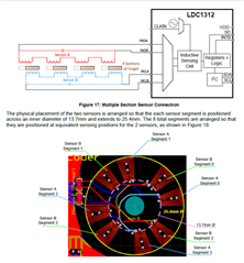
    can you please explain calculation series sensor inductance used in LDC1312 Incremental Encoder Knob. In this inductance is increase by  multiple series inductors. Each of the series elements are placed at an equivalent quadrature positions

    As per sensor characteristic in user guide the inductance is 5.6uH @ 3Mhz with number of turns 6 and 4 section.

    How can we calculate above values using excel tool. do we need to put 6 turns or 24 turns also what will longer and shorter side distance.

    or we need to calculate for one pair and then we can multiply by 4.


    Regards,

    Sayali

  • Sayali,

    The exact details aren't available, but as a guess, the positioning of the four coils allows them to be approximated as individual coils.
    As a starting point, you could try modelling them in the spreadsheet tool as racetrack coils with dimensions approximately equal to the dimensions of the individual coils given in the user's guide. Try adjusting the parameters of a racetrack coil (4 per sensor) so it is approximately equal to 5.6uH/4 = 1.4uH. Four of these coils will be a single sensor. The coil won't be exactly the same as trapezoidal coils shown in the user's guide, but with some experimentation, you can most likely get close.

    Regards,
    John

  • Hello John,

    thank you for inputs. Is there document where calculation is mention for multiple series inductor

    Regards,

  • Sayali,

    The document you have is the only one I know of that addresses series inductors.

    John