This thread has been locked.

If you have a related question, please click the "Ask a related question" button in the top right corner. The newly created question will be automatically linked to this question.

PMP21697: Boost and Buck Leg FET Count

Part Number: PMP21697

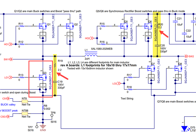
Why does the Buck Synchronous Rectifier switch (Q3) not have a parallel FET but all the other switches are parallelized? Also, what's the purpose of the R19 & C19 and R20 & C20 strings?

  • Hello Marcus,

    Thank you for using the e2e forum.

    Looking at the application, it seems like one FET at the low side Buck leg is sufficient for the give specifications.
    During Buck mode, there are lower currents on the input side in comparison to the output side. Additionally, during Boost mode, the low side FET at the Buck leg is not required and turned off.
    This means there is lower overall current stress on Q3 in comparison to the other FETs and it was possible to reduce cost/resources by using only one low side FET.

    The RC combinations of C19+R19 and C20+R20 are snubbers.
    They are implemented to reduce parasitic effects and EMI radiation.
    The are used at the low side Buck leg and the high side Boost leg.

    Please let me know if there are additional questions.

    Best regards,
    Niklas