


Other Parts Discussed in Thread: INA188
Tool/software:
I have a question regarding this design.
In table 7, it is stated that the PCB Rogowski coil input is 10.7 μV to 1.07 mV (for 10 A and 100 A). VBIAS is also set to 1.25V.
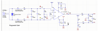
Rg is selected as 100 ohm. So, the Gain of INA188 is 1+ (500k/100) = 501.
So the output of IN88 for measuring sinusoidal current should be (+/- 1.07mV * 501)+1.25= +/- 0.53607 V +1.25 V = +1.78607 and + 0.71393 (1.7807 V for positive peak and 0.71393 V for negative peak of sinusoidal current).
However, in TABLE 8, INA188 output (TP3 – TP5) is written to 0.5328 mV (RMS) AC coupling. Is this a typo?
Best regards,
Mohammad Rastegar.
PhD student at The University of Texas at Dallas.