This thread has been locked.

If you have a related question, please click the "Ask a related question" button in the top right corner. The newly created question will be automatically linked to this question.

UCC25800-Q1: Simulation error keeps coming when i tried to simulate UCC21551 with UCC25800

Part Number: UCC25800-Q1
Other Parts Discussed in Thread: UCC21551, UCC25800

Tool/software:

Hi ,

i was trying to simulate the UCC21551 gate driver section with UCC25800 as power supply to it, Ucc21551 part was working but we i tried integration with UCC25800 it stopped working. am seeing multiple types of error each time. most commonly " there is no data values in section 1 ..., dev/0 error, sometimes it will run for some time like 740E-06 then stops.

i tried adjusting Gmin to 1e-10 which gives : ERROR(ORPSIM-15159): RON or ROFF greater than 1/GMIN for VSWITCH model X_U5.X_U3_OC_Th_Sel_Sample_Hold_S2._U3_OC_Th_Sel_Sample_Hold_S2.

sometimes : failed to open document 

  • Before you bring both models together and before any changes are made, please verify that you can run each of the models individually and they function as expected.

    Steve

  • i tried the both circuits alone, the circuit with ucc 25800 seems having some issues. ucc 21551 am able to simulate without issues. in that case how to sort this  
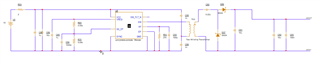
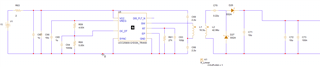
can you identify any errors in this schematic, or pls recommend the simulation profile settings to make this working.

  • Swathin,

    I ran the UCC25800-Q1 PSPICE Transient Model without Sync and it seems to run as expected without any sim errors. I ran the model on PSPICE for TI. I would suggest to start with this model, use the UCC25800 Design Calculator (if not done already). Since I am referring to you to a model that is working on my side, run it "as is" from your side and verify we are aligned. Then carefully modify the TI design to meet your requirements...go slowly, step by step and check the design at each step to make sure it still runs without errors. For example, I see your transformer is different compared to the TI model so I'm not sure how you defined the critical parameters...looks like you have 16.5μH defined as magnetizing inductance but what is the resonant/leakage inductance? 

    Check your schematic - from the pic you attached it shows a connection that might be missing:

    UCC25800 Transient Model PSPICE Schematic:

    Output:

    Steve

  • Hi Steve,

    Thanks for the response , i ensured both models are working normal independently. and now i tried integrating them again still getting some errores

    1.ERROR(ORPSIM-16583): More than one imported model containing transistors or diodes is detected. To simulate this circuit, a minimum of 1 and a maximum of 4 traces are required. Reduce the number of traces and simulate again.

    (i changed the data collection to markers only and limited the number of probs to 3.)

    2, ERROR(ORPSIM-16550): Floating point computation failed during matrix solution. Possible solutions: 1)Ensure that all device parameters are in valid range. 2)Try using .options LIMIT
    .

    Divide by Zero, Divide(0.005, 0)

    ( changed the limit to 1e10)
      

    but still am not able to run the simulation 

  • I'm not familiar with the errors you are describing but there seem to be multiple E2E posts. Just search on the error you are getting followed by E2E ("ERROR(ORPSIM-16583) E2E"). As an example, click the E2E thread here.

    Steve