This thread has been locked.

If you have a related question, please click the "Ask a related question" button in the top right corner. The newly created question will be automatically linked to this question.

SR # 1-819181324 Regarding INA333

Other Parts Discussed in Thread: INA333, TINA-TI, OPA349, OPA347

I am getting no output from the INA333 when testing on a breadboard using a TINA Verified Circuit

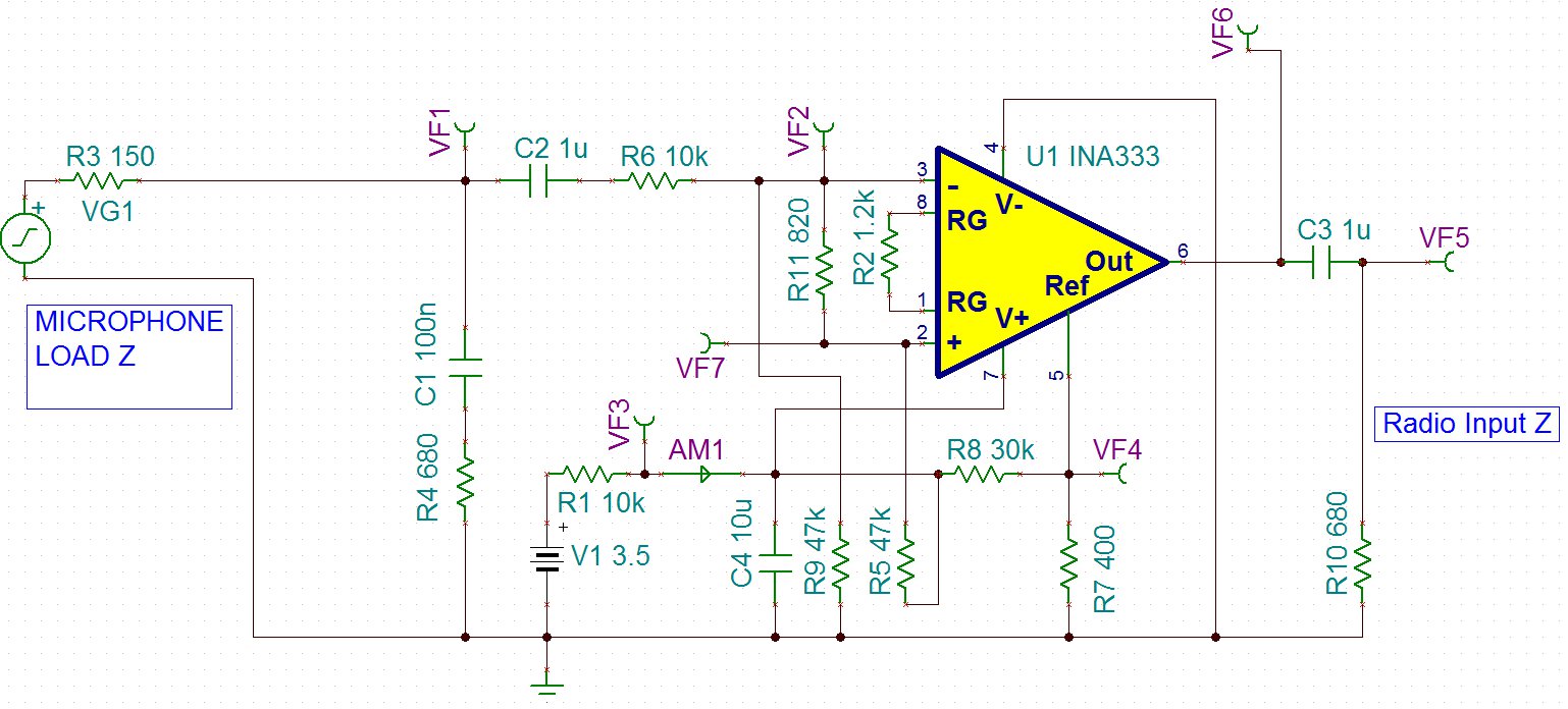
The application is a Microphone Buffer amplifier with unbalanced Input, I have very limited power to work with (single supply between 1.8V-2.2V when the supply is pulled down by the load. I am trying to align Tina-TI simulation with the breadboard assembly.

When trying to assemble on breadboard amplifier has no output. Tina showed that the design under the power supply and load conditions should have a gain of 1.

Real world measurements were used and show that there is a difference in the operating point from Tina-TI, but the amp is still within operating range.

All real world components measure out within 1% while component tolerance in Tina is set to 5%.

Adjustments to resistor values were tried to align real world operating point to Tina predicted operating point with no success.

I have attached images with Tina Schematics. What is preventing me from getting an output on the breadboard? Can you suggest some adjustments to make it work?

  • Hi Dean,

    There are two things about your INA333 application circuit that catch my eye and could be causing the problem. First, it is the inclusion of the R1, the 10 k resistor, in series with the power supply line leading to the INA333. Even though the voltage drop is only about a half volt under the INA333 quiescent current condition, it prevents the INA333 from being able to provide any output drive current. Yes, there is power supply bypass capacitor C4, but that may not be able to provide the required transient current. Also, the combination of R1 (10 k) and C4 (10 uF) creates a long charge time constant that could be a problem at some audio frequencies.

    Second, the output is loaded with R10, a 680 Ohm resistor; a very heavy load for the INA333. The INA333 is specified with a 10 k load resistance and that is a more normal load for the device. Even if the INA333 can provide the required output current (see data-sheet Fig. 29) the output voltage swing may be very limited. An output buffer may be required to drive a 680 Ohm resistor.

    My suggestion is to remove R1 altogether, or make it a much, much smaller value resistor. It shouldn't be required in the circuit and is likely doing more harm than good. The INA333 usually uses a 100 nF power supply bypass capacitor and I would add one at the V+ pin. Since this is an audio application the 10 uF bypass is a good idea too. You would have to adjust the R8 value with R1 removed to obtain the required Vref.

    Simulation models are a mathematical approximation and not a perfect representation of the product's electrical behavior. You may have simulated the application at a frequency where the circuit operated as expected, but had you selected some other condition it may have not. Either way, there isn't anything that compares to the actual circuit and real measured results.

    Regards, Thomas

    PA - Linear Applications Engineering

  • V1, R1 and R10 are set system values and cannot be changed. I tried changing C4 to different values between 10u and open with no luck. Simulation was tested with 1kHz sine wave in simulation and in real life. Will try to add a series resistance at the output.

  • When C4 set to 100n and R10 set to 10K there is still no output. I tried 4 different INA333 chips with the same result.

  • The Simulation only needs to be able to handle 5-20mV in and have a gain of 1. The input must be unbalanced and the power supply and loads are fixed. The most efficient model provided has a current draw of 100uA and is only pulling the power supply down to 2.5V. 

  • Hi Dean,

    I now understand the constraints you have to work within the application. But before we spend more time trying to understand and rectify the observed outcome had with the INA333, are you open to using a device other than the INA333? There is a good probability that we would be able to design a simpler microphone amplifier meeting you needs using a single (or dual) operational amplifier. That approach would likely result in a design with a much lower part count, equal or lower power consumption, the ability to drive the low output impedance and offer some cost advantage over the INA333 circuit.

    Let me know if you are open to this idea and we will proceed from there.

    Regards, Thomas

    PA - Linear Applications Engineering

  • Hi Thomas,

    I am open to a new chip as long as it is already something that it is in your product line and we can get a larger volumes of the chip quickly when the design is finished. If this cannot be accomplished and this chip is the only thing that you currently offer, we have to work with it. Thanks for your help.

    Best Regards,

    Dean

  • Can I use the OPA349 to deliver 5mVpp into 680 Ohm load under these conditions?

  • Hi Dean,

    The OPA349 has a typical 700 nA quiescent current but the price that one pays in return is low bandwidth (12 kHz GBW). It has pretty good output drive for such low operating current and would likely be able to deliver 5 mVp-p across a 680 Ohm output resistor. However, if the microphone application requires  a wide bandwidth response this really isn't the ideal device.

    Regards, Thomas

    PA - Linear Applications Engineering

  • I only need 8kHz of Bandwidth. So do you suppose this will be able to drive the load with the signal within the operating point better than the INA333?

  • Hi Dean,

    The LMV821 has a 220 (typ) to 300 uA (max) quiescent current which corresponds to a 2.2 to 3 V drop across the 10 k power supply resistor. That could be problem with the 3.5 V supply. Otherwise its spec's should work.

    I have a circuit for you that I will post shortly.

    Regards, Thomas

    PA - Linear Applications Engineering


  • Hi Dean,

    Below you will find a microphone amplifier that I designed based on the OPA347. The OPA347 has a typical quiescent current of 20 uA and enough gain-bandwidth to easily support your 8 kHz circuit requirement. I set up the circuit up with a gain of +11V/V so that you can see that you can increase the gain as needed within reasonable limits. Also, it can be set up as a gain of +1 V/V buffer.

    The OPA347 should be able to drive the 680 Ohm load resistor to the 5 mVp-p level required. In the simulations I drove it to something on the order of 100 mVpk with the 680 Ohm load. The R and C values can be altered to adjust the closed-loop gain and the -3 dB, low and high cut-off frequencies.

    I have attached my TINA Spice file for you to simulate. I hope this works for you.


    OPA347_mic_amp_01.TSC
  • Thank You Thomas.  I will let you know how it goes on the board.

  • Hi Thomas,

    This amp is really stable and low power, works great. Thanks for your help.

  • Dean,

    Thanks much for the note saying that the OPA347 is working well in your mic-amp application.

    It was my pleasure to assist you.

    Regards, Thomas

    PA - Linear Applications Engineering