This thread has been locked.

If you have a related question, please click the "Ask a related question" button in the top right corner. The newly created question will be automatically linked to this question.

FilterPro band-pass filter design

Other Parts Discussed in Thread: THS4531, THS4532, THS4521-HT, THS4120, THS4121, THS4521, THS4522, THS4524, THS4130, THS4150, THS4151

Hi

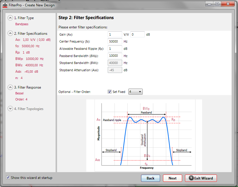
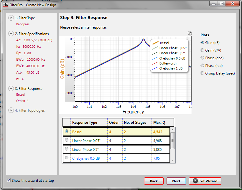
I wanted to design active band-pass filter in FilterPro with:

  center frequency  = 50 kHz

  bandwidth            = 100 Hz

  Ripple                   =  .001 dB

  Pass band Gain  =  1

  differential input and differential output

the FilterPro gives me an ideal OpAmp but I wanted some real part which exists. Could somebody please help me to design smth which is maybe similar to the specs I gave above?

Thanks in advance

  • Shuhrat, This is a very ambitious filter. You may notice that it has a very high Q that is called out. To calculate the appropriate amplifier for your design your filter with, it is critical that you use an amplifier that has at least a bandwith of your 3dB bandwidth (100 Hz) times 100 times Q times your filter's center frequency (50 kHz). You will notice that the minimum bandwidth is several GHz. Typically amplifiers with GHz bandwidths have very high input bias current. This will generate very high DC errors because the input bias current will flow through your resisters causing high output voltage errors. There are two other drawbacks to using an amplifier with such high bandwidths. You will a great deal of signal integrity problems because of this high bandwidth and it will be very difficult to keep your circuit stable because of the high Q value. To solve these two problems I recommend that you increase your bandpass bandwidth.by at least 10x. You would like to have your amifier bandwidth to remain in gain bandwidths of MHz and no larger than a few hundred MHz. Once you modify your design in this way you will find it very easy to find the right amplifier. Please redesign your filter and send me your new specifications. I will help you find the right amplifier.
  • Hi, Bonnie,

    Thanks for your reply. I tried to do as you adviced, but anyway no results

    Here are screenshots:

    Specs

    Responce

    Filter

    It is again givin Ideal OpAmp

    In the examples Folder from Tina Ti I found such kind of filter but for 40 kHz and with ni differential input/outputs. It is here 7532.Ultrasonic 40kHz BPF.TSC .. I wanted at least like this but for 50 kHz

    Regards,

    Shuhrat

  • Shuhrat, Nice job in keeping Q under control. I am anxious to look at your TINA simulation but I don't have this software available to me right now. I will by Sunday afternoon. This will give me a chance to look at your 40k solution. Please look for me then.
  • Shuhrat,

    Thanks for your patience. I am now back at my desk with all of my reference material and there are a few things that we need to fix.

    • the formula for hte BW of the amplifier is actually fo * Q * 100. Please note that the 3dB bandwidth term is not there. This formula makes your amplifier selection much easier. 
    • Your example in the TINA simulation has some variations as opposed to what I think that you are trying to acheive
      • the TINA example has a gain of 40 dB 0r 100 V/V
        • the TINA example is for a standard armplier (not fully differential in and out or FDA).

    In your example above, the minimum GBW required is 24 MHz for your FDA.. There are several amplifier that will fit into the application. These amplifiers are:

    • THS4531 : GBW=36 MHz
    • THS4532: GBW=36 MHz
    • THS4521-HT: GBW=40.7 MHz
    • THS4120: GBW=100 MHz
    • THS4121: GBW=100 MHz
    • THS4521: GBW=142 MHz
    • THS4522: GBW=145 MHz
    • THS4524: GBW=145 MHz
    • THS4130: GBW=150 MHz
    • THS4531: GBW=150 MHz
    • THS4150: GBW=150 MHz
    • THS4151: GBW=150 MHz

    I recommend you look at the slower devices or the ones at the top of this list. Beyond this list, there are more if you want to look at those. Please let me know.


  • Hi, Bonnie,

    Thanks for your reply. I tried with 4531 and it works. And I would like to ask one more thing. Could it be possible to measure the power consumption of that filter circuit with Tina TI? I wanted to measure power consumption in fully operational mode and stand by also. How to do simulations for that?

    Kind Regards,

    Shuhrat

  •  

    Shuhrat,

    If you use the TINA macro model for this device, it is absolutely possible to measure power consumption in both modes. The features of this model are:

    * BEGIN FEATURES
    * OPEN LOOP GAIN AND PHASE
    * INPUT VOLTAGE NOISE
    * UGBW
    * INPUT COMMON MODE VOLTAGE RANGE
    * SLEW RATE
    * tr and tf
    * QUIESCENT CURRENT ON mode
    * QUIESCENT CURRENT OFF mode
    * OUTPUT CLAMPS TO RAILS
    * PWD Mode
    * END FEATURES

    Click here to get the THS4531 TINA-TI Spice Model.

  • I am actually using the spice models you showed. I have 4th order BPF with two stages using THS4531 and am doing transient and AC analises of the circuit, but I cannot figure out how to measure power consumption for the whole circuit both in active mode and stand by. I have seen power meter in Tina but don't know how to use it for measurements. Could you give som hints?

    here my circuit 6457.diff_50kHz_BPF_3dB_gain.TSC

    p.s. we have different time zones... :-)

  • Shuhrat,

    You are right, there is a power meter in TINA. When you measure, the current path is left-to-right and voltage is top-to-bottom. I have used it before successfully in this configuration. I hooked up your circuit, while looking for the power on the supply voltages. See attached.

  • Bonnie,

    Thanks for the reply. According to the datasheet for 4531:

    Ultra Low Power:

    • Voltage: 2.5 V to 5.5 V
    • Current: 250 µA
    • Power-Down Mode: 0.5 µA (typ)

    Does it mean that for 5 V supply Power consumption is 5*250uA=1.25 mW (active mode) and 5*0.5 uA = 2.5 uW (power-down). The device is featured as an ultra low power.

    And if we see from the simulations, the Power is: PM1 = 5 mW and PM2 = 438,84mW. Does not it seem to be high for this kind of device. And how to measure power consumption in power-down mode?

    Kind Regards,

    Shuhrat

  • Shuhrat,

    I can see your issue with the power dissipation. If you were only looking at the amplifier in a static condition these power values would be wrong, however you are driving the inputs with voltages. The amplifiers are responding accordingly.

    As for measuring the power down mode again you need to just look at the amplifier, with no load or input signal. AS you do this measuremnt in SPICE, configure the PD pin to the right voltage to force a power down stae.

  • Bonnie,

    If I drive the Pin PD to Ground then PM1=505,2 nW and PM2=510,12 nW. I think the results are correct, or....?

    If I simulate without input signals (PD is driven to VDD) then the results are as previuos (PM1 = 5 mW and PM2 = 438,84mW). Do you think that the device consumes so much power? Are these values correct or is smth. wrong...? For the total power should I add up these PM1 and PM2?

    Regards,

    Shuhrat

  • Shuhrat,

    For the total power you should add the two power figures together, however I am still concened about your second stage. It is running too hot. I am curious. What are the values of the ouput pins (out+ and out-)? And as you look at that, what is the value of the stage one output pins?

  • Bonnie,

    I don't really understand what you mean by running too hot.

    Input to the filter is 50 kHz sine wave with amplitude 800 mV, direct output of the first amplifier is the same wave with amplitude 600mV (this sine wave after register at the seinput of the second stage is very strongly attenuated), and the output of the second stage is the same wave with amplitude 1 V.