This thread has been locked.

If you have a related question, please click the "Ask a related question" button in the top right corner. The newly created question will be automatically linked to this question.

Webench Designer Rdson & PdCond values are 0 in Op Vals report - actual efficiency may be much lower than stated.

Other Parts Discussed in Thread: LM25116, TPS40170, CSD18503Q5A, CSD18504Q5A

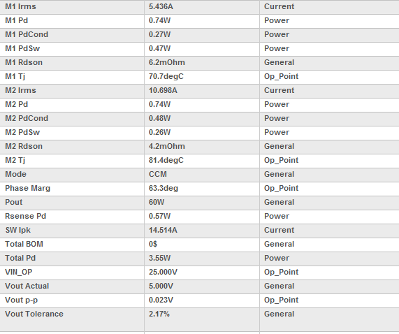
Below is a link to an LM25116 design I'm working on. M1/M2 Rdson & PdCond values are 0 in the Op Vals report. Is this a bug or am I missing something?

This is my first post. Is this the proper way to post a link to a design? I used the Share Design feature before but don't know how to post a design to this forum.

webench.ti.com/.../webench5.cgi

  • David,

    Actually, that is the proper way to post a link to the design. However, when I open it, all of the values are calculated:

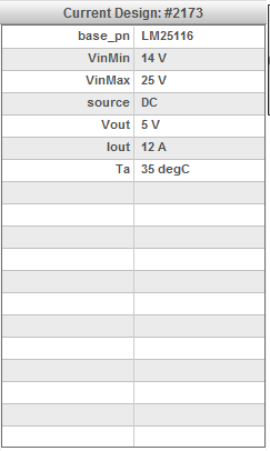
    Here is the design description that opened:

    Could you try to open the link yourself (not by accessing your original design, but from the public share link) to see if this works for you?

  • Britt,

    When I open the design from the link above all values are calculated as you found.

    Regards,

    Dave Brent
  • Britt,

    I just noticed that the entire design was regenerated with different components, frequency, etc. so I think my problem is related to the components in my original design. If you open my DesignId=66 I think you'll see the 0 values.

    Thanks,
    Dave Brent
  • I think the problem is related to the Infineon BSC340N08NS3 G FETs. It is only when these FETs are used that Rdson=0 & PdCond=0 in the Op Vals report. The RDSon values look OK in the schematic editor. Are ohms and mohms being confused somewhere?

  • Dave,

    A couple of things. First, evidently you placed a link to the "default" design created from the product folder. In order to public share the design you had created, use the share design feature and select Share with Public. This will create a link that you can cut and post into the forum that will allow us to pull your design directly.

    Second, I have confirmed the issue with the design and I have sent it to one of our developers to evaluate. Not sure of the root cause yet, but the efficiency plots and some strange numbers occurred when I was playing with the OpVals at different currents and voltages. I do suspect something in the FET library, but I cannot be sure yet.

    Thanks for point this out and for your patience as we evaluate the issue.

  • Britt,

    Thanks for the "Share with Public" info. I hadn't noticed that option when I shared the design with George Peterson (our local TI AE) previously.

    Do you have any outlook for when this will be fixed? We have a board spin going to layout next week and I'd like to get any changes in beforehand, if possible.

    Thanks,
    Dave

  • Dave,

    Our team is looking at it now. Evidently, it looks like some of the data in the database for the component was missing from an update for the component. I'll let you know as soon as I have an update. Apologies for the delay.

  • Dave,

    We think that this issue was corrected a couple of days ago with a release. I need a little more information about how the issue occurred:

    1.) When you originally designed the circuit, was the error present, or did it occur more recently after a change in the design?

    2.) Could you re-generate the design from the start (I think the bug will go away), or is that not an option now?

    3.) You mentioned that this was a board spin. What updates were made? Were components or targets changed?

    Thanks for any additional information you can provide.

  • LM25116_24V_to_5V_10A_Regulator.pdfBritt,

    Attached is my original 10A design from January which didn't have the error. It requires ~100us to fully recover from a 1A-to-10A load transient. Recently I attempted to improve the transient response by optimizing for "Smallest Footprint" or changing the frequency to 1MHz. Both yielded designs that used Infineon BSC340N08NS3 G FETs which have a very low Qg (required for faster switching) but higher RDSon. I then increased the output current to 12A which was the highest current achievable at 1MHz. At the end of last week I noticed the Rdson & PdCond values were 0 so I generated a completely new design with the default "Balanced" optimization. This design also used Infineon BSC340N08NS3 G FETs and had Rdson=PdCond=0. This was the design I referred to you (Design ID 66).

    I generated new designs today and 222KHz & 340kHz are now the highest frequencies available at 10A & 12A, respectively. The Infineon BSC340N08NS3 G FETs are not used in these designs and Rdson & PdCond appear to be correct. Faster transient response, which requires lower L and higher f, would require very low Qg and Rdson to keep the switching and conduction losses reasonable. These parameters appear to be inversely related in reality: small FET = low Qg & high Rdson, large FET = high Qg & low Rdson. Is there another way to improve transient response with the LM25116 or a different controller? Since we are spinning the board I have one last chance to change this regulator circuit.

    Thanks,

    Dave

  • Hi Dave,

    Please accept my apologies for the inconveniences you faced with WEBENCH design creation between July 25th-August12th.  If you re-created your original design(from January) between July25th-July29th you should have run into the Rdson'0', Pcond '0' error. A temporary fix was placed on July29th, where you could not replicate the Rdson'0' issue any more, but the design perhaps didn't make sense between July29th-August12th.

    A proper fix related to Rdsons was released on August 12th and what you see now in your designs is what you can expect.

    I have re-created your original design from 1/21/16 with optimizer knob=2 and FSW=270kHz and below is the new pdf report along with the new design.  You may notice that the power dissipation from FETs has slightly changed from your original report , this is correctly reflecting the updates we have made to the FET database recently for TI NexFETs. Overall efficiency has shifted from 92.101% in January to 92% now reflecting again, the FET updates.

    Now it seems that your goal is to improve transient response using LM25116 or with another choice of controller.

    Have you checked with Optimizer knob=2 and with 14-25V Vin @ 5V Vout and 10A load, TPS40170 tops our list of solutions?

    See the design for TPS40170 for same 10A spec at 340kHz https://webench.ti.com/webench5/power/webench5.cgi?DesignId=9233&base_pn=TPS40170&app=

    and compare it to LM25116 at 340kHz for the same conditions. https://webench.ti.com/appinfo/webench/scripts/SD2.cgi?ID=179910::power::p-jella@ti.com

    TPS40170 seems to show faster during startup and you may try other sims as well for comparison. While you view these, I am also check with sim teams to see if there are ways to improve transient response for LM25116 for your design spec. We will get back to you.

    Best Regards,

    Pavani Jella

    WEBENCH Applications

  • Pavani,

    Thank you for the detailed feedback and suggestions. We are spinning our board and it is in layout this week. At this point I can only change the compensation components.

    Last week I created a new LM25116 design here: https://webench.ti.com/appinfo/webench/scripts/SDP.cgi?ID=12CB392A8105D63C with FSW=300KHz. This frequency enabled selection of 2x 10uF/2mohm ceramic input caps and a 3.3uH XAL1010 inductor which has 3.7mohm DCR in a small package. The 3uH inductor options at 340KHz were comparatively large and switching losses were higher. The new design also uses a CSD18504Q5A for the upper FET which has lower Qg than the CSD18503Q5A in our original design. This lowers losses at the low duty cycle (21-22%) this circuit operates at. These 3 changes lowered Pd at 24V, 10A by ~850mW.

    This new design has 61 degree phase margin @ ~38KHz crossover vs 46 degree @ ~45KHz of our original design so its transient response is worse. Britt mentioned that a crossover of 1/5th the switching frequency (~60KHz) would provide better transient response. Can you suggest compensation components for this new design that would optimize the ransient response?

    Thanks,

    David Brent

  • Hi David,

    To improve your transient response, the Rcomp and Ccomp values need to be adjusted. You'll want to increase the Rcomp value slightly and decrease the Ccomp value. The Rcomp increase will boost the Xover frequency, while the decreased Ccomp value will allow for a faster transient response.

    I tried values on the sim and it gave a transient response similar to your original design.


    (Old Rcomp = 3.92kohm)

    (Old Ccomp = 15nF)


    New Rcomp = 4.99kohm

    New Ccomp = 3.3nF

    Xover frequency = 46kHz

    Phase Margin = 42deg

  • Pavani's prior reply answered the original question I posted. Kevin's most recent reply answered a follow on question I had regarding transient response.