This thread has been locked.

If you have a related question, please click the "Ask a related question" button in the top right corner. The newly created question will be automatically linked to this question.

TINA/Spice/OPA335: how to create different voltage

Part Number: OPA335
Other Parts Discussed in Thread: TINA-TI, REF3040, REF3240

Tool/software: TINA-TI or Spice Models

Hi Sir

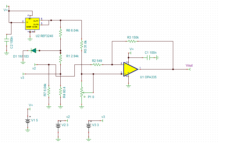
sorry for i have no idea how to create different voltage to replace thermocouple volatge, may you pls have idea for us?

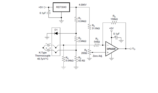
and beacuse there is no REF3040 in libary, so i use REF3240 to replace. is it also ok?

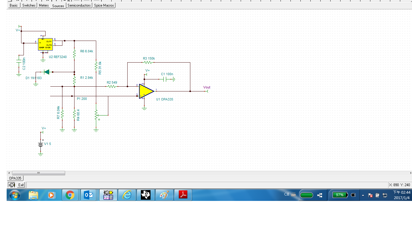
And I have try use V2 is 3V, V3 is 3.004096V. but i found Vout alway is 2.5V. whatever i change Radj(P10), Vout always 2.5V.

Is something be limitation?

  • Chen,

    Lets re-visit what you are trying to simulate in TINA-TI. Here is your original circuit picture:

    So, my first question is what do you want this circuit to produce? What should the Vo be for the circuit? You should have some kind of expectation of what the output will look like based on the varying the temperature at the sensor.

    Next, how much of a role does the REF3040 device play in the output? If it is only being used as a 4.096V precise voltage value (no changing of the Vin to it and the circuit will not draw too much current that would cause the Vref to go unstable), then I would replace it with a fixed voltage source of 4.096V. If you must have the REF device, the REF3240 is very similar to the REF3040 and should be fine.

    Next, there is not a model for the Thermo couple, but we know that It simply provides a voltage based on the temperature provided. That differential voltage is given by (Temp*40.7uV/C), so at 0C, the value is 0. At 100C, the value is 4.07mV. You can connect a voltage source between the two pins and set the value to whatever the temperature requires. Alternatively, you could sweep the voltage value using the Select Control Object feature in TINA-TI or you can use a time based source and define a temperature vs. time waveform to use. This is your choice.

    Finally, what is the potentiometer being used for? Is it for adjusting the circuit so that the zero value is set? If so, I would not use a potentiometer here as once it is set, the resistance value is constant for your simulations. I would figure out what the resistance value is and use a fixed resistor for it. The potentiometer is shown for the actual circuit in calibrating it for the non ideal values in the circuit. The simulation does NOT need this.

    This is the approach I would take for find the correct simulation using TINA-TI. Since I do not know most of this information about your application, you will need to define this and create the schematic accordingly.

  • Hi Sir

    May we know if we can add thermocouple model in Ti-Tina?

    If yes, how to put in TI-Tina.

                                                         Bogey