This thread has been locked.

If you have a related question, please click the "Ask a related question" button in the top right corner. The newly created question will be automatically linked to this question.

TIDA-00626: not able to program LMX2592 using USB2ANY

Part Number: TIDA-00626
Other Parts Discussed in Thread: USB2ANY, LMX2592, , LMX2592EVM

respected,

i have developed the reference design of TIDA-00626. but i am not able to program the LMX2592 IC using USB2ANY. i made a thread on LMX2592 they addresed me on working of LMX2592 but were unable to address the debugging procedure for TIDA-00626. i am unable to power down the device using TICS-pro software and at the same i am unable to lock the VCO . i would first like to say you what testing i have done.

1. the power supply section of TIDA-00626 is working perfectly and giving me all appropriate voltages.

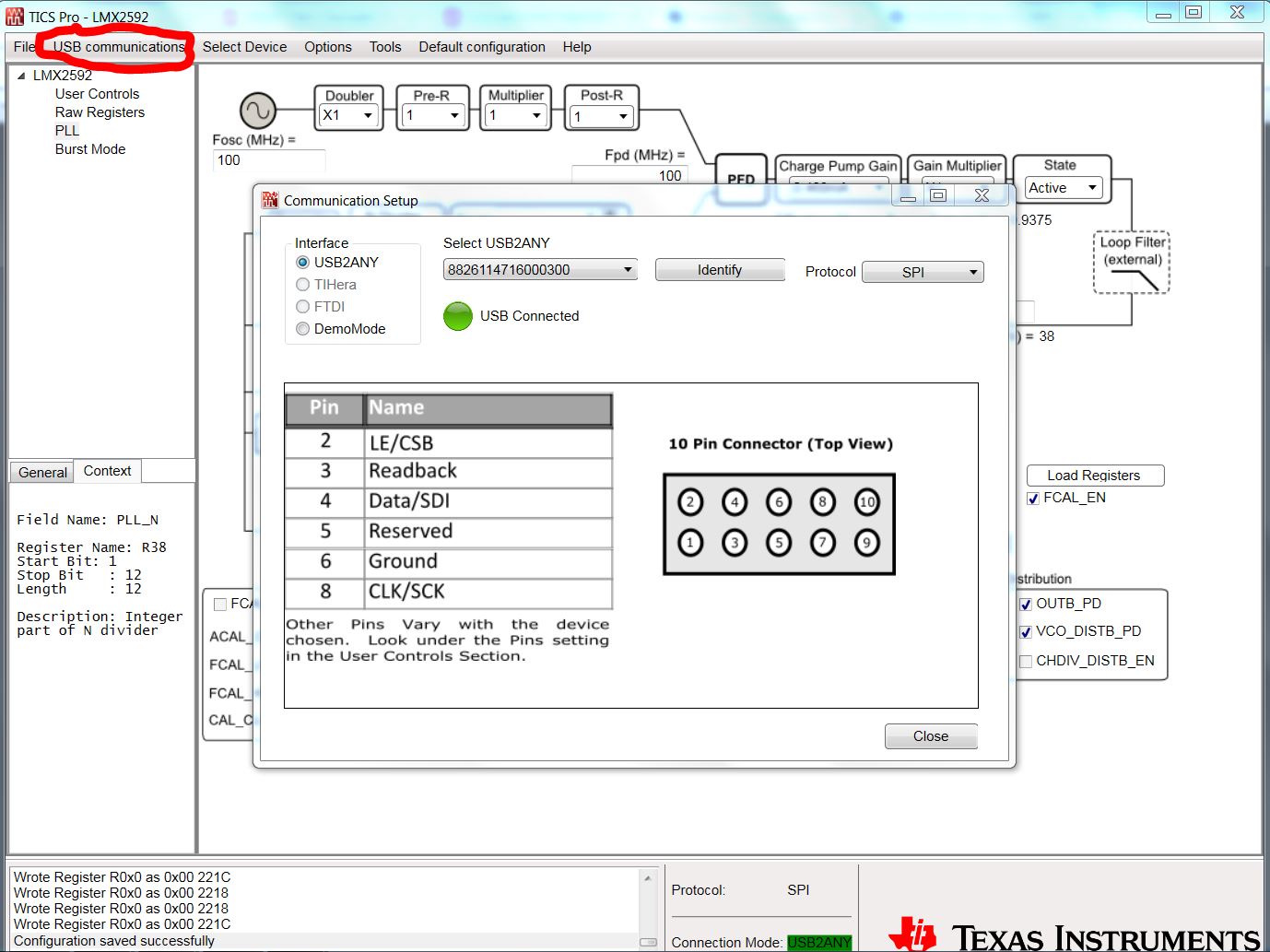
2. My USB2ANY is also working properly tested it by using TICS-PRO software and pressing the II=identify button and USB2ANY green LED blinks.

3. connector for USB2ANY is placed properly.

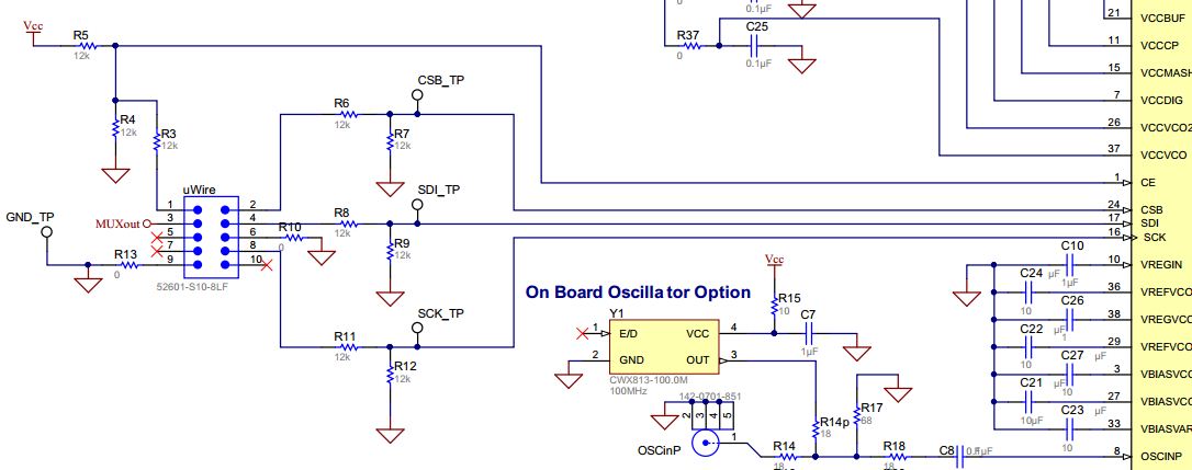
4. i have disconnected r15 and r13 from the board as i prefer using the on board crystal oscillator of 100 MHz.

5. the power consumption of board is arround 400-450 mA but the specified power consumption is of 750 mA is this fine. 

5. as specified in LMX2592 forum the said me trie to power down the device and eventually your current consumption will reduce and the voltage at OSCin pin will drop to 0(power down) and is 1.6v(powered up). but i am not able to power down the device.

please help me to debug this fault of USB2ANY connection so that i can get my signal generator working. please mention steps to debug the circuit.

kindly address us as soon as possible any help will be highly appreciated.

  • Hi Pratik,

    Yes, initial power consumption of TIDA-00626 board is around 400 mA and the specified 750 mA current is max. So your board is consuming proper current.

    If LMX2592 power down pin is not working, it seems device is not programming through SPI. 

    Few points for debug:

    1. Ensure TICS Pro is detecting USB2ANY, as shown in attached image.
    2. Probe SPI signals at SPI test points (CSB_TP, SDI_TP, SCK_TP), while programming the LMX2592.
    3. After disconnecting the R13 and R15, make sure R11 is connected for on-board crystal path to OSCin.
    4. Probe at R11 and check the crystal output coming proper (100 MHz). 
    5. Make sure, you are following the "LMX2592 Software Start-up Instruction" section on page 13 for programming the LMX2592.
    6. I have attached the example config file of LMX2592. Please import and check in TICS Pro. After programming, power consumption increases to around 560 mA.

    LMX2592_Config_File_Example.zip

    Hope, it resolve your issues.

    Regards,
    Ajeet Pal

  • respected,

    i appreciate the info provided i am still not able to power down the device using USB2ANY.

    i would like to request you to address my following doubt.

    i observed the circuit diagram of LMX2592EVM. i look at the USB2ANY interface in LMX2592EVM which is as follows.

    now when i compare this with the reference design  of TIDA-00626. which is as follows.

    my concern is that in the reference design the resistors marked as DNP why are those resistors used for. should i connect them or should i disconnect them . and if we need to connect them than why we have not done such configuration on LMX2592EVM noard. can these resistors cause any issue in programming of the board.

    kindly address my doubt

  • Hi Pratik,

    The above mentioned resistors also DNP in LMX2592 EVM, same as in TIDA-00626 board.

    Just wanted to check, are you getting the SPI signals at SPI test points, while programming the LMX2592?

    Disconnect the R14 resistor from CE pin, it shows CE is having pull up and pull down at same time. Also remove R37 resistor.

    Regards,

    Ajeet Pal

  • respected,

    following the circuit diagram and and following your instruction after the removal of DNP resistors i was able to lock the VCO in the initial configuration and the green led at MUXout turned up right. thank you for this support. i will be testing the output on spectrum analyser soon.

    i would like you to address some of my doubts.

    1. is the heating of IC LMX2592 normal when in the locked state.
    2. do i need to test any other volatge parameters after the VCO is locked.

    i also have some issue using the tics pro gui i will be making new thread for that kindly address me to help me with it
  • i would like to request some help in configuring the board for higher frequency. As you provided us with the default configuration which gives the output of 1.8 GHz. i was looking forward for some higher frequency. the issue lies in TICSPRO gui.

    at initial configuration the VCO gets locked properly and MUXout LED lights up but when i change the 'RF outA' in ticspro GUI to some other value the vco comes out of the locked state.

    kindly help me that how can i configure the LMX2592 for higher frequency and how to lock the VCO at higher frequency.
  • Hi Pratik,

    It's a good news, you are able to program LMX2592 using TICS Pro.

    Regarding to your doubts:

    1. I think, its normal to heat LMX2592 device, when you are enabling RFoutA/B.

    2. No other voltage parameter test is needed, once your VCO is locked. LED1 is good enough to show the VCO lock status.

    Regards,

    Ajeet Pal

  • respected,
    thank you for your continuous support.
    i am now able to successfully lock the VCO at any desired frequency and also tested it on the spectrum analyzer i will soon post the results too.
    i am making a plastic enclosure for the device and for the same i will be attaching jumper wires to uWIRE interface to the conncetor of USB2ANY so that there is no strain or pressure on the actual PCB board.
    Also i want to take the output by connecting jumper wires to the output on the board and connecting it to the SMA connector.

    My concern is can i use normal multi stranded wire to connect to the OUTPUT and GND what precaution should i take so that i dont get noise in the output. i was also thinking to make a jumper of OUTPUT by 0.1 mm laminated copper jumper wire to the SMA connector. kindly guide me for the same
  • Hi Pratik,
    Using the jumper wires for USB2ANY connection, it should not be the issue. But taking RF output using jumper wires is something need to look.
    Generally for RF signal (high frequency) interface, jumper should be make of RF cables, which is 50ohm coaxial cable. These cables are cut at both ends and connect center conductor to RF trace and outer conductor to adjacent ground. After connecting as jumper, still it will not give exact 50ohm transmission (impedance mismatch). Hence, you will see some output powder degradation.

    Regards,
    Ajeet Pal
  • thank you,
    i will take care of that.
    i wanted to know do you have any idea about how to program the digital attenuator MAAD-011021 which is on this board
  • Hi Pratik,

    I have responded on #674327 thread for the digital attenuator MAAD-011021 programming.

    Regards,
    Ajeet Pal