Other Parts Discussed in Thread: OPA2348-Q1
Hi Guys,
I have a question about TIDA-01513 Automotive High-Voltage and Isolation Leakage Measurements Reference Design.
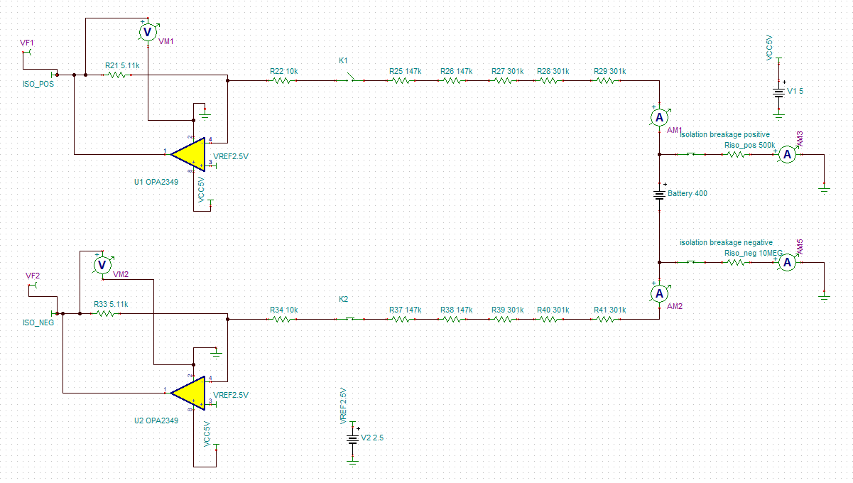
We are running simulations in TINA for isolation leakage measurements. The problem that we have is that we are trying to measure what will happen if there is an isolation breakage on both positive terminal and chassis and negative terminal and chassis. We can calculate the isolation resistance if there is an isolation breakage on only one terminal and chassis and isolation resistance between other terminal and chassis is neglected.
For example, If there is an isolation resistance of 500kohms between positive terminal and chassis and the isolation resistance between negative terminal and chassis is neglected the accuracy of isolation resistance between positive terminal and chassis will be below 5%. The same case is if it happens between negative terminal and chassis.
The problem is that there will always be some resistance between positive terminal and chassis and negative terminal and chassis.
For example if there is an isolation resistance of 500kohms between positive terminal and chassis and isolation resistance of 10Mohms between negative terminal and chassis, the accuracy will be around 17%.
Is there some way that we can do accurate calculations of resistances between the positive terminal and chassis and negative terminal and chassis with this method if both resistances are included?
Simulation method in TINA can be seen in the picture below.
Thank you.
Best regards,
Vedran