


Other Parts Discussed in Thread: LMG5200
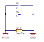
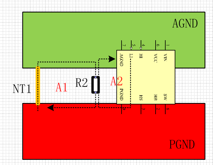
In order to avoid the interference of power part to signal part, NT1 is used as the connection point form AGND to PGND.In order to make the driving signal electrically stable relative to the power ground, two resistors, R 1 and R 2, are placed in the design.
I have the following questions. I look forward to your help.
1.Are the above descriptions of NT1, R1 and R2 correct?
2.Why not add three resistors and put under every LMG5200 to reduce the area of A2?
3.Why choose NT1 instead of zero ohmic resistance for grounding control power supply?
4.Why NT1 is not closer to 48V input to reduce the effect the fluctuation of PGND potential level by high current ? For example, short circuit current.
Thank you and look forward to your reply.


