This thread has been locked.

If you have a related question, please click the "Ask a related question" button in the top right corner. The newly created question will be automatically linked to this question.

PMP20859: Questions about PMP20859

Part Number: PMP20859

Hi experts,

     As we know PMP20859 can support up to 3 inputs, two are PSE, one is DC Jack.

     Now customer is going to use PMP20859 as base to modify for their customer.

     1. They would like to remove DC Jack, what components can be removed?

     2. For input caps, we can see there are two 47uF caps on one TPS2372-3, can we remove one?

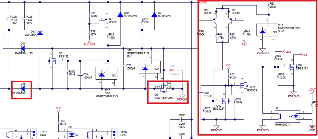
    3. Can you explain how the circuit works in the red box? and why it needs D16 and Q11? and what is the function of U2 in this circuit?

    Thanks a lot for your support always.

Best regards, Cage.

  • Do you have any update?

    Sorry for pushing...

  • 1.  (D18, C32, C33, C34, L5, L6, J7) (R69, D24, C40, R74, R76, R77, Q15, U6) (R34, R39, R43, Q7, D17, D10, Q8, R100, C29) (R60, R65, R66, Q13, D19, D25, C39, R101, Q14) can be removed if not using the DC jack.  I have not operated the circuit without these components so it is important to fully test this configuration.

    2.  No, both 47uF capacitors are required.  If one PoE input is powering the converter at a lower voltage and the other PoE input is then connected at a higher voltage, current from the two 47uF capacitors charges (C31, C100, C101) (C47, C48, C49) to the higher voltage.  If there is not enough energy available the voltage may droop causing the PoE PD to go into in-rush mode and the smooth transition would not function.  It is also important to not add significantly more capacitance in parallel with (C31, C100, C101, C47, C48, C49).

    3.  The circuit in the red box is a level shift for the PG signals.  PG1 and PG2 are on different returns, both of which are different from PWRGND.  Optocoupler U2 disables the PG/SS circuits whenever the output is powered.  D16 (D26) blocks the voltage from the opposite PoE to allow detect and classification.  Without these diodes the input bridge would be reversed biased and the PoE could not connect.  Q11 (Q16) are used to disconnect the PoE inputs from the DC jack, allowing the PoE to stay connected in MPS mode.  They may not be required if not using the DC jack.  I would leave them in the schematic and test to see if they are needed.

  • Hi David,

         Thanks a lot for your reply.

         It really help.

    Best regards, Cage.