This thread has been locked.

If you have a related question, please click the "Ask a related question" button in the top right corner. The newly created question will be automatically linked to this question.

TIDA-01512: Requirement of the inductor on 12V at the input.

Part Number: TIDA-01512

Hi,

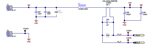
  1. I am following the reference design provided from TI for the generation of core and DDR voltages of my LS2 design. In the reference design there is an inductor on the 12V rail before the current sensor resistor. The part number suggested is HCB65-550X from delta electronics with description as Inductor, 55 nH, 30 A, 0.0002 ohm, SMD. I have checked for the online availability of this product and found that this product is not available. I have tried to find an alternate but could not get it. So kindly please let me know whether this inductor is can be removed from the circuit and the 12V can be directly connected to the power stages by having only the decoupling capacitors. If the inductor is compulsory please suggest me a part that meet the design requirement. 
  2. Also please let me know whether the removal of the inductor effects the accuracy of the input current sensing.

Below is the part of the schematics where the inductor has been used.

  • Hi Sai,
    The inductor is part of the input filter to help ensure a clean VIN for the converters further down the line.
    You can substitute this with any similar 50-65nH inductor with the same or larger current rating without any problems.
    We've used this one in the past:
    https://www.itg-electronics.com/files/c8c9d917b6461b5a097af459101cf4d8.pdf

    Changing the inductor value or removing it won't affect current sensing.
    -Xavier

  • Hi Xavier,

    Thanks for your reply.
    I have place constraint on my board, so I am planning to have only decoupling capacitors of 22uF and 560uF in parallel. I am trying to get the 12V from the external power supply. Please let me know whether that will be fine.
    I am not able find the inductor suggested by you on online for purchase.

    Thank you once again and please let me know regarding the decoupling option which I want to implement.
  • One reason to have this sort of input filter is to reduce line noise that comes from other devices on the board suddenly drawing large amounts of current from the same 12V line.
    It all depends on how comfortable you are with line noise and variations.
    What is the maximum total current that you are expecting to draw in your application?
    In this reference design, for instance, the maximum current drawn on the 12V will be 15A. You could safely use a 50nH inductor rated for 20A, which will probably need a smaller footprint than the 55nH inductor that we use in our reference design.
  • Hi Xavier,

    We are designing this power section for LS2088A. The total expected current from the power supply is 29A from 12V rail(for our whole circuit). We are implementing this multiphase solution solely for LS2088A core voltage and DDR voltage for DIMM module and LS2088A. We are supplying the 12V from a COTS power supply. So I am checking for this line filter requirement for the multiphase power stage devices.

  • It sounds like you have multiple devices drawing large amounts of current from the 12VIN line. I would recommend a filter, like this one, for each high current rail.
    For example, If you have multiple rails controlled by TPS53681s on your board, have an input filter circuit like this for each high current rail (Vcore1, Vcore2, DIMM, etc.). That way if one set of powerstages suddenly draws a lot of current, the noise on the line will be minimized on the other rails. 

  • Hi Xavier,

    Thanks for your support. 

    We are using SLC7530S-500MLC from coil craft, as a replacement for the inductor available in the reference board for the line filter. It is 50nH and 40A capable SMD inductor, So please suggest whether this would be proper replacement or not.

  • That looks like a good substitute.