This thread has been locked.

If you have a related question, please click the "Ask a related question" button in the top right corner. The newly created question will be automatically linked to this question.

WEBENCH® Tools/LMZ12003: Output voltage in transient analysis is not as set by the feedback resistors

Part Number: LMZ12003

Tool/software: WEBENCH® Design Tools

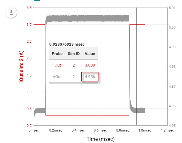
Hi , When simulating LMZ12003, using default values for feedback resistors ( Vout =5V, so RFBT=5.062Kohm, RFBB=1.07kohm ) the load transient waveform shows steady state at 4.096V instead of 5V . the resistors when using formula from the data sheet should set voltage to 5.0018V. Could you explain the difference?

  • Hi Sebastian,

    Can you please share your design public URL here? We can take a look at the waveforms then for different testbenches like steady state, load transient, etc. The image you attached did not come through.

    Regards,
    Amod
  • Hi Amod,
    Thanks for taking the case, the link is below
    webench.ti.com/.../SDP.cgi
    Sebastian
  • Hi Sebastian,

    I see ~4.96V for steady-state output voltage when I ran the simulations. The feedback resistor design usually just tries to provide an output voltage closest to 5V but if you want the gap bridged and Vout > 5V, you can easily do that by either bumping up Rfbt a notch higher or lowering Rfbb a notch down to the next standard value. Hope that helps answer your question. Let me know if you need the exact Rfbb/Rfbt values that can help provide Vout >5V.

    Regards,

    Amod

  • Thanks Amod,
    The currently chosen resistors should provide (data sheet eq. 2) Vout = 0.8V*(1+Rfbt/Rfbb)= 0.8*(1+5.62/1.07)=5.0018691.
    So I guess we should see the 5V in steady state not 4.096? I have tried 0.1% resistors but this does not affect the results.
    Sebastian
  • Hi Sebastian,

    I see your point on 5V steady state value for Vout - that is correct. I see the feedback voltage in the simulation model is modeled as a variable function and it changes from an almost no load current value of 0.8V to about 0.793V when full 3A load current flows through the IC. So, at 3A with this design you actually see Vout = 0.793*(1+5.62/1.07) = 4.958V. This is consistent with the datasheet electrical characteristics table value of VFB on page 5. I am requesting a product expert to look at this and comment if there is a change that needs to be made in the simulation model or if we need to size the feedback resistors differently.

    Regards,

    Amod

  • Hi Amod,
    Fantastic spot I have missed that , let see what product expert is going to say.
    Sebastian
  • Hi Sebastian,

    There will be part to part variation with all devices. As such the datasheet specs the feedback voltage to have a min, typ, and max value as Amod has shown above. Please see the following:

    • Vfb_min = 0.773V ; Vout = 0.773*(1+(5.62/1.07) = 4.833V
    • Vfb_typ = 0.793V  ; Vout = 0.793*(1+(5.62/1.07) =  4.958V
    • Vfb_max = 0.813V ; Vout = 0.813*(1+(5.62/1.07) = 5.083V

    Assuming that the 0..1% resistors do not affect output voltage variation, the feedback voltage variation will result in a +/- 2.5% of the typical output voltage of 4.958V. Also I don't believe the simulation is an issue since Amod was able to simulate a load transient with 3A step and the output voltage was 4.956V which is expected.

    Can you reconfirm that the simulation you provided gave you an output voltage result of 4.096V or was this a typo?

    Regards,

    Jimmy 

  • Hello Jimmy,

    Thank you for your answer,

    Indeed it is a typo we talking about 4.96V , as per simulation I have shared.

    I do accept that if we take onto account the Vfb tolerances , the steady Vout would not be exact 5V since we can not assume 0.8V Vfb.

    Thank you for your help

    Sebastian