


Hi,
I have used the TIDA-01292 reference design in my board for an inverter, the design is just great :) , thanks for that.
But in my output stage i.e the H bridge output, i have connected a 10mH and 22uF capacitor (i know its huge, wanted to have a low cutoff - around 1k) for filtering the SPWM wave.
I m getting distorted sinewave...... i.e there are alot of low frequency harmonics(100Hz, 150Hz,etc), What i want to say is....i m not getting a pure sine wave no matter what filter i do.
So , i asked our expert, he suggested that there is some issue with modulation method itself, i m worried now, because i thought TIDA- 01292 design was a pure sinewave generator.
Please suggest if some changes need to be done in modulation for getting a pure sinewave or suggest value of filter for getting pure sinewave.
I m attaching images from my oscillloscope with FFT analysis done on it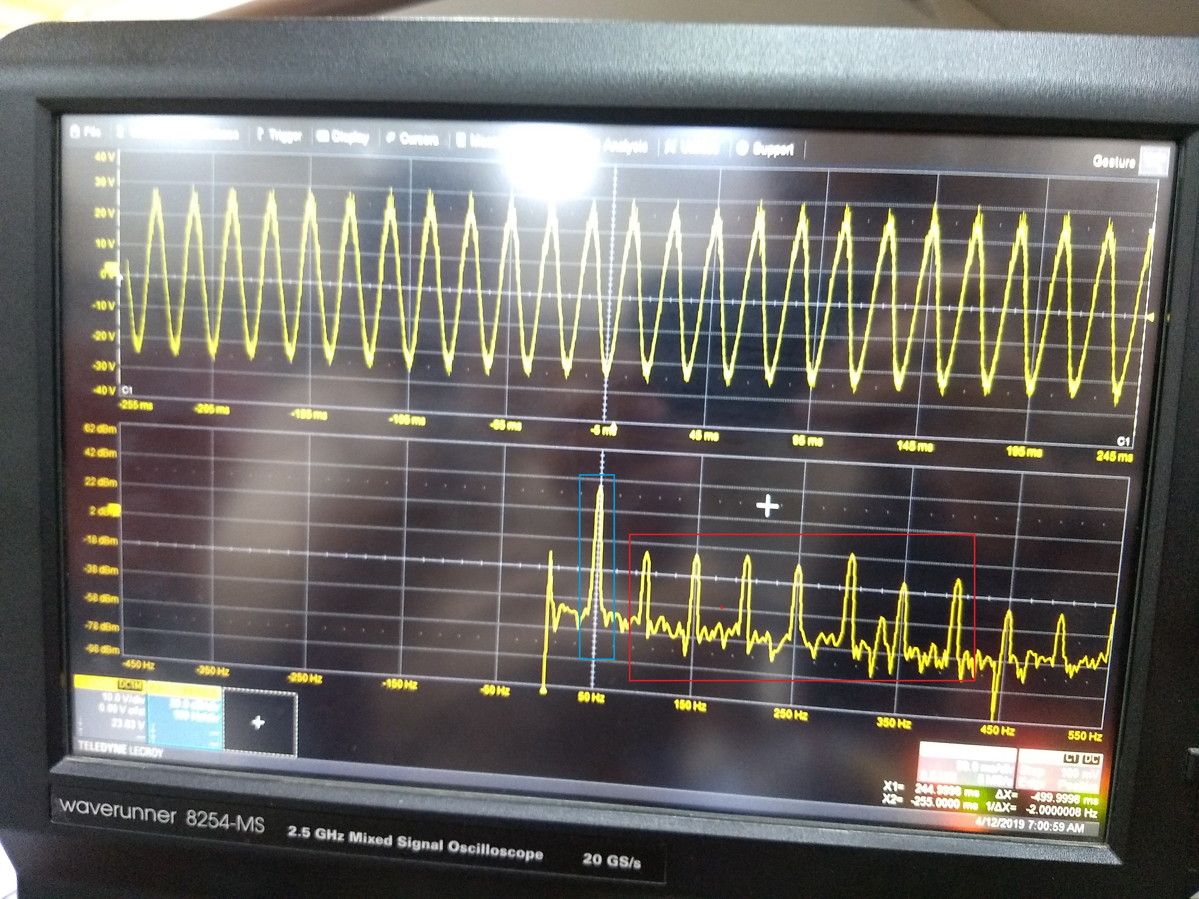
Here the blue rectangle is the signal it is having ~40dBm power, but you can also see the red rectangle box with 100,150,200,250Hz harmonics, i m worried about these.......please ignore the high frequency component on the signal....i will tune that part....

this is the zoomed up version, we can clearly see the distortion of 50 Hz signal, i.e it is not pure sine wave.....pls note i m not not talking about the high frequency ripples , i m talking about the shape of the sine wave.
Please help me resolve the issue, as i m unclear as to where the fault lies (modulation technique or LC tuning)...

