This thread has been locked.

If you have a related question, please click the "Ask a related question" button in the top right corner. The newly created question will be automatically linked to this question.

TIDA-01292: Sine wave result of the model having low frequency harmonics

Part Number: TIDA-01292

Hi,

I have used the TIDA-01292 reference design in my board for an inverter, the design is just great :) , thanks for that.

But in my output stage i.e the H bridge output,  i have connected a 10mH and 22uF capacitor (i know its huge, wanted to have a low cutoff - around 1k) for filtering the SPWM wave.

I m getting distorted sinewave...... i.e there are alot of low frequency harmonics(100Hz, 150Hz,etc), What i want to say is....i m not getting a pure sine wave no matter what filter i do.

So , i asked our expert, he suggested that there is some issue with modulation method itself, i m worried now, because i thought TIDA- 01292 design was a pure sinewave generator.

Please suggest if some changes need to be done in modulation for getting a pure sinewave or suggest value of filter for getting pure sinewave.

I m attaching images from my oscillloscope with FFT analysis done on it
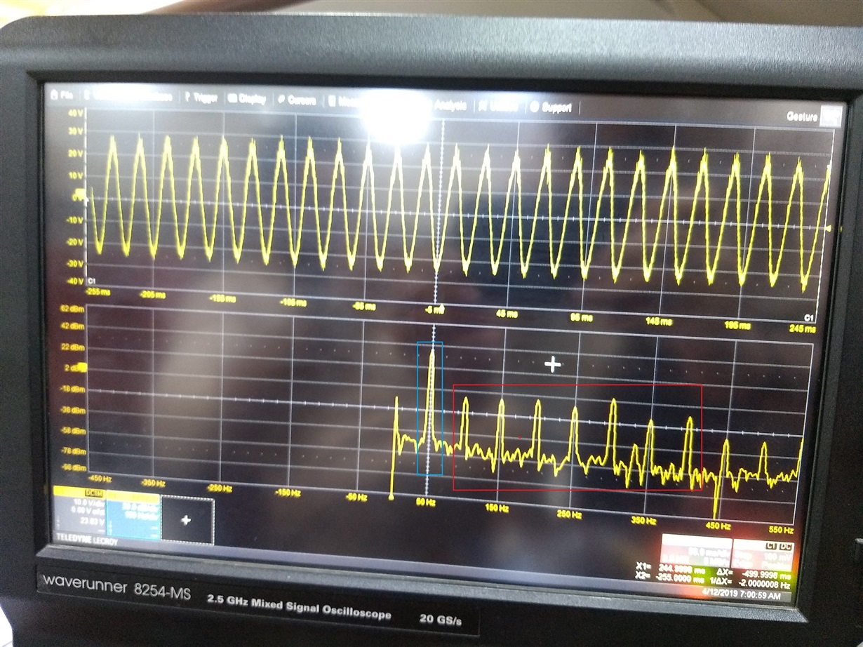
Here the blue rectangle is the signal it is having ~40dBm power, but you can also see the red rectangle box with 100,150,200,250Hz harmonics, i m worried about these.......please ignore the high frequency component on the signal....i will tune that part....

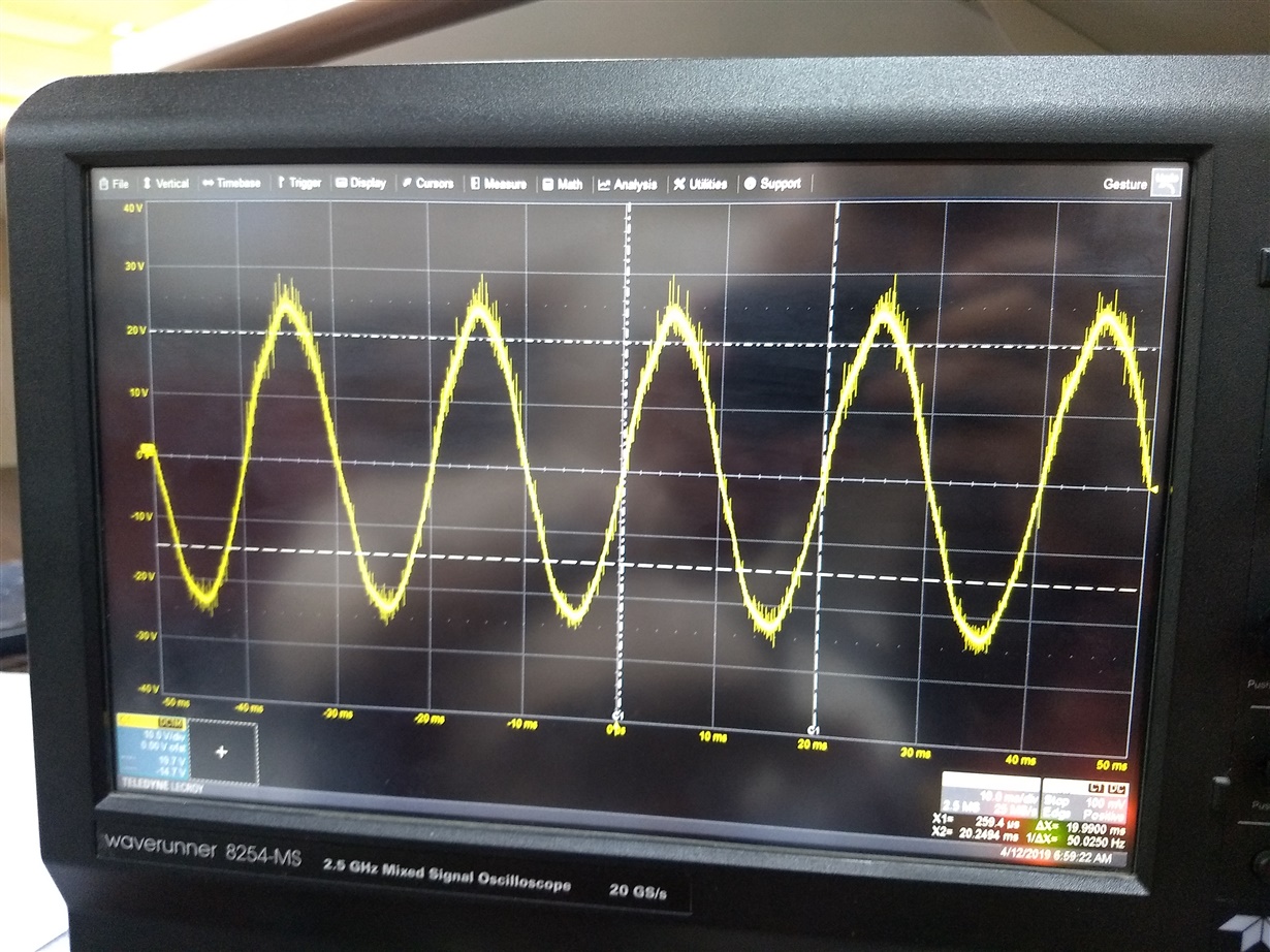
this is the zoomed up version, we can clearly see the distortion of  50 Hz signal, i.e it is not pure sine wave.....pls note i m not not talking about the high frequency ripples , i m talking about the shape of the sine wave.

Please help me resolve the issue, as i m unclear as to where the fault lies (modulation technique or LC tuning)... 

  • Hi Rajat,

    The problem may be due to modulation. However, the sine PWM code should be tuned to correct this type of problem with different values of inductor - capacitor combinations. The TIDA-01292 is just an inverter power stage - the output of it will depend on how we modulate the PWM.

    Regards,

    Salil
  • Sir, 

    Please suggest me where should i correct it , i mean which parameter in modulation (if it is modulation). Isn't TIDA01292 a pure sinewave inverter??

    Could you please suggest L and C values, as i have tried many...but i m not able to remove these low frequency harmonics. Kindly help

  • Hi Rajat,

    TIDA-01292 can work as a pure sine wave inverter, provided the code can be corrected to suit the external components. It was designed for offline UPS application, where the harmonic distortion was not a very serious problem. If we add correction parameters to the code, you can get a waveform with very low THD. The hardware has no constraint preventing it.

    Regards,

    Salil
  • sir, could you please elaborate, where the improvements need to be done, i.e.if switching frequency should be increased or sine function for calculating duty cycle needs to be modified.
    Kindly give a clear idea, on what needs to be changed in the present design.

  • Hi Rajat,

    There are a lot of literature available online about improvement of THD in voltage source inverter by modified SPWM, THIPWM (third harmonic injection PWM), SVPWM (space vector PWM) or even more advanced PWM control techniques. As these are much beyond the scope of this design, we haven't explored further in this direction.

    Regards,

    Salil