This thread has been locked.

If you have a related question, please click the "Ask a related question" button in the top right corner. The newly created question will be automatically linked to this question.

CCS/TIDA-00721: TIDA-00721 problem with using RF430CL330H

Part Number: TIDA-00721
Other Parts Discussed in Thread: RF430CL330H

Tool/software: Code Composer Studio

Hello All;

I've been using the reference design but the NFC chip didn't detected by mobile or NFC reader, 

I used the same code and schematic in the reference but nothing!

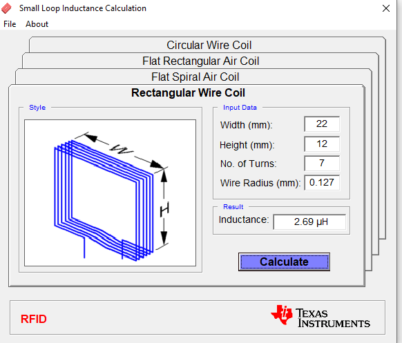
I used both rigid and flexible PCB, and I used LCR to measure the L of the antenna and found that it gave around 630uH on the rigid PCB but when I calculate the tuning capacitance for that it gave (~34-35pF) different from what shown in the reference design (39pF), is this the issue!

I consider the internal capacitance of the NFC chip in my calculation (35pF) but I mean the result gave minus -34pF

what I can do!    

  • Dear enng -
    I am not suprised, as the recommended inductance for the RF430CL330H IC antenna coil is 2.66uH (@13.56MHz).

    630uH is far too high of an inductance to use with this part. (or at this frequency, for that matter)

    Please adjust your inductance and retune.

    Also, use an LCR meter which is running at least 10MHz or better yet, use a network analyzer to measure the coil exactly at the right frequency it will be operating at. (which is 13.56MHz) - then apply tuning cap

    For reference, see www.ti.com/.../rf430cl330h.pdf (section 4.4) and www.ti.com/.../sloa197.pdf.

    also, it seems impossible that you got 630uH on a PCB...here attached is a little application that might be handy for you. 

    We made this for quickly figuring out size and # of turns needed for tag coils. It is based on idea we got from this online tool - with frequency added (in the background)

    Calculate_L.zip


    Do not hesitate to come back for more help if needed.

  • Hi Josh

    Thank you very much for your reply and details

    The idea is that I cannot change the antenna as already on PCB but my question is that I used the design reference from TI, so the pcb exactly the same! I knew this 630u is too big then why I got it with TI pcb reference design!

    What I have done to measure the inductance if you have a look in schematic I remove both 0 ohm resistors and both diodes to isolate antenna from any connection and then use LCR with swipe frequency and got 630uH ?  I probe on both end of antenna.

    Regards  

  • Dear enng - can you provide a picture of your creation and the schematic? to measure the coil, you will need to connect it to an LCR meter which is running at HF band, close to 13.56MHz...this would be pretty rare...usually they are running at 1kHz or 100kHz and not much use for this kind of work. Next least expensive option is to use an MFJ meter ==> like this one , and (power supply) to measure the complex impedance (R + jXL) and inductance

    next option is to use a network analyzer  - use the Smith Chart and measure the R + XL directly that way - see attached app note i wrote (for the ISO15693 tags, which have slightly different coil requirements) but never released - 

    page 30 for image of example of that, then make sure you see page 37 on how to measure it and check the resonant frequency and Q value, too HF-I Tag Antenna Design Application Note_11-08-26-013_Rev_0.pdf

  • Hello Josh,

    Thank you very much for your answer and details,

    Please see schematic and reference design:

     http://www.ti.com/lit/df/tidrm48/tidrm48.pdf

    http://www.ti.com/lit/ug/tidubt8/tidubt8.pdf

    from schematic, I remove R1, R4, D1 and D2 to measure the only L of the antenna using LCR, probably I done something wrong with my measurement! but I mean I used 39pF (C5) as seen in schematic and use the same antenna from the design but the NFC didn't detected at all! my PCB is the same exactly as shown in reference! I tried 4 boards but couldn't detected the NFC! 

    Regards

  • I also would like to ask one more question, I knew that the C6 is used for storage but is this will affect the tuning or not!

  • Dear ennng -

    if you removed R1, R4, D1 and D2, then you have isolated the antenna coil for measurement and C6 will also not be connected, so it would not impact the measurement, either.

    Then, since you have removed the parts I made red box around, you should then be able to measure the coil directly from the two points i have the blue oval around. 

    Did you make any modifications at all to the layout? or did you just have someone make reference from the Gerbers provided? Please use one of the methods I suggested to measure the coil you made and start from there. This is the only way to make sure what you got back was what you ordered to be fabricated. 

  • Thank you for your reply

    Yes that is exactly what have done to measure,

    I will try what you have suggested. I am just wondering about storage capacitance, is this will affect the overall capacitance? I mean in operation while every component on place? because what I have seen in some references  they only consider the internal capacitance of NFC (35pF) and external capacitance for tuning to get around  13.56 MHz. But in our case if you see schematic I guess the storage capacitor will affect  as seen as  parallel capacitance ?

    Regards

  • Dear ennng  -

    in order to further assist you - i went and found a sample of this TIDA and measured it with the Helmholtz coil I made just now (to make sure, for sanity check)

    so - if you want to send me an email at: josh.wyatt@ti.com  - i can send you my mailing address and you can send me a PCB so i can check it - i have all the equipment here needed and this would be very easy for me to do - then all doubt can be eliminated and you can proceed forth with your development. 

  • Hello Josh;
    Thank you very much.
    I will do.
    Regards