This thread has been locked.

If you have a related question, please click the "Ask a related question" button in the top right corner. The newly created question will be automatically linked to this question.

TINA/Spice/LMP7721: PSpice simulation issue (Edit: It's about LMP7731, sorry for the mistake)

Part Number: LMP7721
Other Parts Discussed in Thread: TINA-TI, LMP7731, LMC6001, OPA316

Tool/software: TINA-TI or Spice Models

Dear community,

I'm currently simulating a design with the LMP7731 amplifier and I got simulation issues in OrCAD PSpice (I'm using version "17.2-2016 S048"). I got the following error message:

ERROR(ORPSIM-16550): Floating point computation failed during matrix solution. Possible solutions: 1)Ensure that all device parameters are in valid range. 2)Try using .options LIMIT
INTERNAL ERROR -- Divide by Zero, Divide
ABORTING SIMULATION

You'll find attached my test bench. If I try the test bench provided with the model, it works fine. Then I modify it to let it work in single supply with an offset to half supply at the input, then it does not converge any more. Your help to get this design converge will be highly appreciated. I try the "AUTOCONVERGE" option but it doesn't resolve the problem and I also don't like this solution as it relax some parameters and simulation accuracy is lower.

Kind regards

Etienne Haenni

LMP7731_test.zip

  • Hi Etienne,

    We are looking into this and get back to you.

    Regards,
    Saket
  • Hi Etienne,

    There are 2 things that I can see is an issue,

    1. Why are you providing ICs (NODSET) at the -ve nodes of the Opamp in AC model

    This needs to set in automatically by the loop negative feedback in OP .

    Enforcing voltages here is incorrect and can cause potential contradiction.

    2. Also the DC blocking capacitors that you have used just to block the DCs and pass the ACs (based on what I understand) is suggested to have a much bigger value in spice simulation.

    Please use 1F Caps there. Because the AC source you are using is also having DC offset and if a fraction of it also gets passed it will lead to OP contradiction as well.

    Try these 2 changes and let us know.

  • Dear Ahana,

    Thank you for your input. I try to simulate my final application which is a 2nd order bandpass filter at 72.3 Hz with a certain gain. In my app, the signal source has a DC offset of 0.8V. So increasing the input to 1F will just give a complete different response to what I'm looking after and in that case it does not make sense anymore for me to simulate this schematic.
    My issue here is that the simulator cannot find the OP for any type of simulation (TRAN, DC, AC, ...). I try many other amplifiers (OPA316, LTC6268, LMC6001, ...) and it works well, except with this one I will use in my design. This is why I do my best to get it working. Once I get it working, I'll do all my wanted analysis: AC&Noise, TRAN-Noise, FFT, ...
    If I connect the positive input to '0' and supply the amp with +/- 1.65V (dual supply) it works well. As I have an AC coupling I can do this "supply shift" to get the simulation working. But for my next simulation step, with the next stage connected at the output, I'll need to supply this amp with single supply and 1.65V at positive input to get my DC offset at the output.

    I remove the two nodeset from my simulation and it doesn't change anything. BTW, I don't think I'll teach you something, but a "NODESET" is not an "IC". With a nodeset, you "suggest" an OP to the simulator, you don't "force" an OP. If this suggestion does not help the simulator, it just doesn't take care about it. I used this option many times with "Mentor ELDO" or "Cadence Spectre" when I was designing ASIC's and it helps me a lot of time.

    Kind regards,
    Etienne
  • Hi Etienne,

    Looking at the circuit I felt specifying the node voltages were not needed because I couldn't find any reason to provide the same here. So it felt to be on safe side to remove it if at all it gives some unwanted spice issue.

    And removing these 2 NODE-SETS along with increasing the cap value (which I guessed might be only for blocking the DC) solved the error, hence I suggested the same.

    I really don't know about your application but for LPF, we ideally don't need that input capacitance .

    As you are mentioning that this model can never find a OP can you share in which other cases it is failing to find the OP? It will help me analyze the issue better.

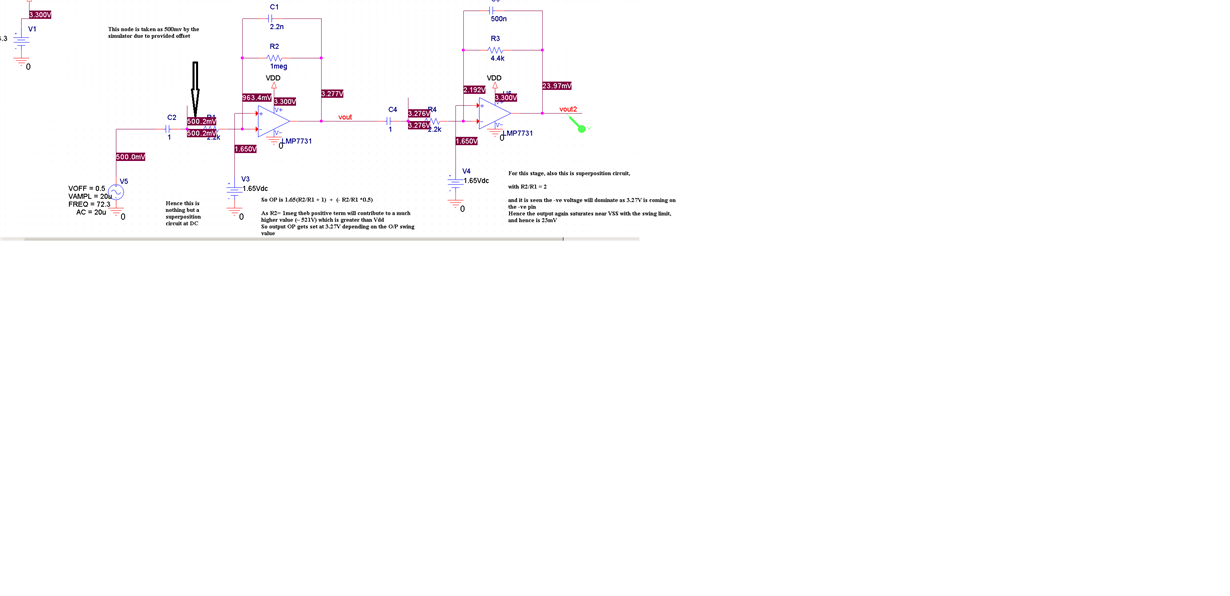
    As far as I simulate and observe the node voltages I don't see any improper behavior by the model LMP7731. Please see my comments below,

  • Dear Ahana,

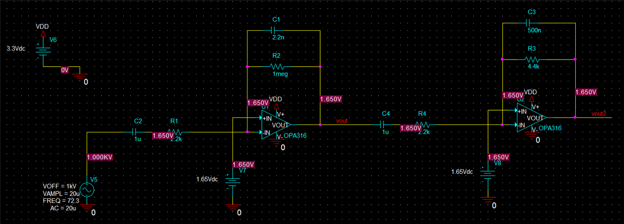
    Thank you, you just demonstrate that the LMP7731 does not converge correctly. The OP of your simulation is completely wrong. A simulation that run to the end does not mean the result is correct.

    Here is the simulation with an OPA316, a model which work correctly. Notice that the OP is everywhere 1.65V as you would measure on a real circuit in steady state. Please also notice that I put 1kV of DC offset for my signal source with 1uF and the simulator can find the OP without problem in few millisecond. As I am designing a BANDpass filter, I NEED the input cap at 1uF for the HPF behaviour of the filter. 1F is completely out of the scope.

    Best regards

    Etienne

  • Hi Etienne,

    I understand your concern. Actually what I meant in the last comment was the OPs that were showing in PSpice is correct, if I consider the first node in the left of R1(2.2k) which is seen to be at 500mV to be correct.

    As the moment I can see 0.5V coming in to that node, I will say the Cap(C2) is failing it's job to block the DC(which may be due to many issues) and hence I said that I suppose model is fine.

    What you said is correct it should be 1.65V and hence I checked more on it.

    Currently  looking at the behavior we suspect this might be because of 'sim parameter' issue in the PSPICE tool itself. 

    As I checked the same circuit with the same LMP7731 model in TINA-TI and it works as expected. [.TSC TINA schematic file  attached below for your reference]

    So it's behaving different in PSPICE is what we currently see. TINA-TI is a free simulator and you can download it from ti.com to check this for now.

    LMP7731 Test Circuit.TSC

    Regarding the PSPICE we will be looking more and surely get back to you.

  • Hi,

    We’re trying to resolve this, unfortunately, this is not an easy one for us to debug, so it will take us a while to resolve this.
    Unfortunately, we don’t have timeline visibility as to when we will be able to resolve this issue. Apologize for the inconvenience.
  • Dear Ahana,

    Thank you for the feedback. Good luck for the debug.

    Best regards,
    Etienne