This thread has been locked.

If you have a related question, please click the "Ask a related question" button in the top right corner. The newly created question will be automatically linked to this question.

TIDA-01418: Confusion in Fault protection circuit in the reference design

Part Number: TIDA-01418

Hi,

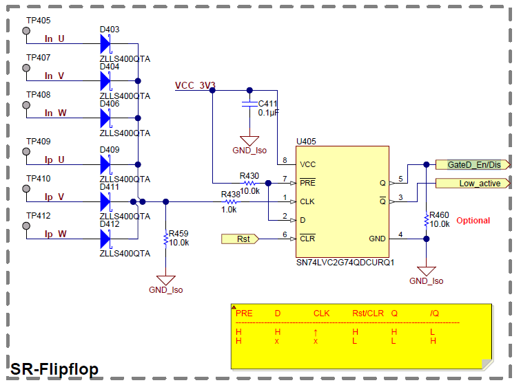
I have confusion or need clarification regarding the protection circuit that is given in the TIDA-01418 Automotive high voltage, high power motor driver reference design for HVAC compressor reference design. The SR flipflop is used to latch the fault and disable the Gate.

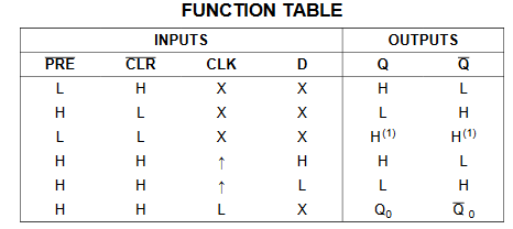
Here, my question is when there is a fault (CLK=H) and the user pressed reset Rst (CLR'=L) then the output is given low (Q=L; enable gate). The output should be high (Q=H; disable gate) if CLK = H i.e. during fault irrespective of other input states. 

  • Hello Sandeep,

    I think your concern is valid if the user could manually clear the fault signal or if the system would autoretry without making sure the fault is gone.

    But in the case we are looking here, the clear signal is required to be able to restart the system and can only be sent by the MCU.

    Looking at the function table from the datasheet, we have:

    • the output will be set high on the rising edge of the CLK signal (as /PRE and D are always pulled up high). 
    • If /CLR is not use, the output will then always stay high whatever is the sate of CLK (as /PRE and D are always pulled up high)
    • The only way to set the output to low is then to use the /CLR (as /PRE and D are always pulled up high)

    Once the output of the SN74LVC2G74QDCURQ1 is set high, the PWM would stop to be sent to the half bridge, thus clearing the fault. The MCU should then, after making sure the fault condition is gone, send the /CLR signal to be able to restart the system.

  • Hi Kevin ,

    Thank you for your reply.

    What I will do is I will make sure that the /CLR will be a short pulse either from MCU or manual reset. Even if the user not sure the fault is not gone or accidentally pressed reset, the output of SN74LVC2G74QDCURQ1 will be set high since the /CLR becomes high after a short duration. 

  • Sandeep,

    If the fault is cleared once, the same fault will not be detected a second time. This is because the output of the SN74LVC2G74QDCURQ1 will be set at the D level (high in our case) on the rising edge of the CLK signal, meaning that if a fault is still present, the CLK will not see another rising edge for the same fault. so if /CLR is used, the output will not be set high when /CLR goes high again.

    I think a safer way to implement a manual fault reset is that the manual reset is send to the MCU and the MCU set the /CLR only when it is safe to restart the system.

  • Hi Kevin,

    I want to separate the MCU and manual reset. When MCU hangs, the setup has hardware protection which is completely isolated from MCU. 

    Do you suggest any other suitable solution for this? 

    Thank you.

  • The protection is independent of the MCU but to restart the system the MCU would have to be involved.

    If the MCU is hanging, the PWM generation would also be hanging. So clearing the fault and re-enabeling the gate driver without resetting the MCU may not be optimal.

    the /XRS pin of the MCU can be used for resetting it.