This thread has been locked.

If you have a related question, please click the "Ask a related question" button in the top right corner. The newly created question will be automatically linked to this question.

TIDA-01421: Obtain a signal when driving motor with relays (continued)

Part Number: TIDA-01421
Other Parts Discussed in Thread: DRV8703-Q1EVM, INA240

Hello again!

I am making this thread in continuation to the old thread e2e.ti.com/.../889204 (TIDA-01421: Obtain a signal when driving motor with relays)

Since my last post, I have obtained a new TIDA-01421 board and I am now using a DRV8703-Q1EVM board to drive the sunroof motor.

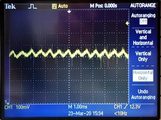
Here is the output from U2 pin 5

Is this an expected result of the amplification? I am still not receiving a good signal at the timer pin.

Thanks in advance!
Gunjan

  • Gunjan,

    I assume channel 1 in your scope shot is the PWM voltage signal, and channel 2 is the output of the INA240 on the TIDA-01421 board (U2-5).  Is that correct?

    If so, it looks like you have 50% duty cycle at (about) 20 kHz.  Could you take a similar shot with no PWM (100% duty cycle) so we can see the ripple current without the PWM spikes?  You will probably need a longer time scale to see the current ripple.

    -Clark

  • Hello Clark,

    Thank you again for your response. You are right in your assumption. Channel 1 is output from the DRV8703-Q1EVM board set at around 50% duty cycle, and channel 2 is the output from INA240 on the TIDA-01421 (U2-5).

    In my previous thread (here), I had posted a scope shot of the U2-5 pin where you believed that the output did not show an amplified signal.

    Below is another image, although at a higher voltage resolution.

    Let me know what you think.

    Thanks,
    Gunjan

  • Gunjan,

    If the current on R6 still looks likes the below image from your earlier post, then I expect the same shape at U2-5, which I don't see in the trace above.  So it seems  like your INA240A1 is not amplifying the voltage as expected.  That is where we need to start debugging.

    Suggestion for debug: Disconnect the TIDA-01421 board from the motor, and apply a small signal (for example from a signal generator) to J1-1 with ground on J1-2.  See if the signal is amplified on the INA240 output (U2-5)

  • Hello Clark,

    I separately applied small sine (frequency 1kHz, amplitude 100mV) and square wave (frequency 1kHz, amplitude 100mV, 50% duty cycle) signals to J1-1 and J1-2 according to your suggestion. Unfortunately there seems to be no amplification at U2-5 and the output on the scope is a horizontal line at about 2.5V, very similar to what can be seen in my previous thread. I tried this with two different TIDA-01421 boards, but it's the same result on both.

    How should I further proceed with troubleshooting the INA240? Should I apply some other signals (or change the parameters) from the function generator?

    Looking forward to your reply,
    Gunjan

  • Gunjan,

    Did you remove the 3 milliOhm resistor (R6) for the above measurement?  If not, it is probably loading your signal generator to the point that the signal is negligible.

    Also, when you are running the motor, I want to make sure you are connecting so that you are forcing all the motor current through R6.