This thread has been locked.

If you have a related question, please click the "Ask a related question" button in the top right corner. The newly created question will be automatically linked to this question.

WEBENCH® Tools/SN65HVD1782: RS485

Part Number: SN65HVD1782

Tool/software: WEBENCH® Design Tools

Dear Sir,

Sir we are using SN65HVD 1782 IC for Rs 485 communication with my controller.we have total 40 nodes linked in a daisy chain to each other at a length of about 25 meter.

sometimes in between we start getting garbage value like null character and some random character from the port through which all the devices are connected. Due to which we face a problem in data transmission.and device didn't respond as per the data

The specification of the wires used is 120 ohm. un shielded twisted pair of RX and TX.

4 core, 24AWG (0.22 sq.mm) 2X2X0.22 stranded RS485 cable 0031320 Unitronic Li2YCY (TP) from LAPP

What could be the possible reason for this.?Because it comes randomly. no such pattern observed till now.

Please looking for your prompt response

  • Hello,

    Is it possible to start by observing the A and B signal waveforms on an oscilloscope when the garbage data is present? That should give us some clues as to whether this is a signal integrity issue on the bus or something else.

    Max

  • Dear Sir,

    The application is already out in the market.We observe this issue when we move with numbers.

    The time we tested individually such problem was not there. But when we move with numbers like 30 nodes at 25 meter with wire specs as given in trailing conversation we get some instances of garbage.Garbage is any ASCII character.

    We cannot have the oscilloscope reading for the same.

    Can you help us he possible way out why such type of issues can arises based upon your experience with RS485 on wire

    Looking for your prompt response

  • In general using 40 nodes at a distance of 25 m should not be an issue for an RS-485 network.  Is the total network length 25 m, or is 25 m the distance between each node (giving a total length of 25 m * 40 = 1 km)?  (1 km is generally achievable as well, although you could run into baud rate limitations depending on the AC losses of the cable.)

    Do you know whether the issue is with existing ASCII character transmissions getting corrupted, or is it with additional characters being detected that are not expected?  If it's the former then it implies a signal integrity issue, if it is the latter it may be something else like noise coupling.

    Would it be possible for us to review a schematic of the RS-485 implementation?  Particularly I'd like to understand how the DE lines are controlled (it is important to make sure only one transceiver on a shared bus is enabled at any given time), how termination is implemented, and whether any failsafe biasing is used.  Can you also please let us know what baud rate is used and if any other baud rates have been tested?

    Regards,
    Max

  • Dear Sir,

    Total length is about 25-30 meter max and having total nodes 40.

    Baud rate is 115200, Not tested any other baud rate

    Yes, At the time of transmission and receiver the useful data is Numeric and Hexadecimal but additionally we get some random characters and null values as shown below.

    Garbage we receive like :    z–0.vìš-±¬¥s.°,0ËÜ,0ÖŸ4,0,0,0,0, 

    But actual result should be 4,0,0,0,0,  The starting charterer are garbage.Mostly it comes at starting side and in middle of the actual data.

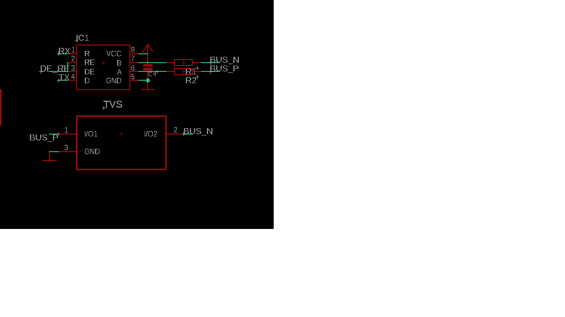
    RX,TX is connected to Controller. directly to controller

    DE,RE also connected to controller. (directly to controller)

    Bus N and Bus P is the RS485 signal which is carried out in a daisy chain structure in next nodes. (Series connection)

    Attached is the sch

  • Thanks for the info.  That's very strange.  Disregarding the random garbage data, are you able to receive the proper messages (e.g., 4,0,0,0,0) from all nodes?  If so then it doesn't seem to be an issue related to signal integrity over the network.  If that were the case, I would expect for messages to be corrupted in some repeatable way - for example, certain data patterns or certain node-to-node paths always resulting in a similar error.

    So, I wonder if there may be some noise that is coupling onto the bus when it is operated in the field.  This could affect the bus when it is supposed to be "idle," resulting in the UARTs seeing an errant high-to-low transition on R and interpreting it as the start of a word (and then decoding any subsequent random toggles as these random ASCII codes).

    If this is the root cause, there are a couple of things that could help.  One is use of termination.  Is any termination implemented currently?  (If so, what is it?)  This reduces the differential-mode impedance of the bus and makes it more difficult for there to be differential-mode noise present.  Common-mode noise can generally be rejected by an RS-485 transceiver, but if there are excessive amounts that could be reduces as well by using a modified "split" termination network (described further in this blog: https://e2e.ti.com/blogs_/b/industrial_strength/archive/2016/07/14/the-importance-of-termination-networks-in-can-transceivers).

    Another way to boost the noise immunity in the idle state would be to use external pull-up and pull-down resistances to bias a high-level differential signal on the bus.  You can read more about this technique (often referred to as failsafe biasing) in this blog: https://e2e.ti.com/blogs_/b/industrial_strength/archive/2016/12/06/rs-485-basics-two-ways-to-fail-safe-bias-your-network.

    Regards,
    Max  

  • Dear Sir,

    We do not use any of the termination in this application.

    Termination could be the only reason for this.?

    Also

    1. We have devices which are connected in Daisy chain connection.We have a total 40 nodes.connected in series of approx 25 meter length. we have connected the device through wire.

    The connection architecture is as below :


    Wire----Device1(PCB)-----wire-----device2(PCB) and so on


    Device1(PCB) has the track of input signal and out signal to device 2.through the wire


    Also we have used wire impedance of 120 ohm.and it goes through the Device1(pcb) to another Device2(pcb) through track +wire as shown in blue colour above.

    Now there are instances where we get some garbage while transferring and receiving the data.Is it because of an impedance track change in pcb and wir

  • Hello,

    Yes, my theory is that the random garbage data may be the result of noise coupling in the system when the bus line is idle (all nodes in receive mode).  In this case the input differential signal:

    1. will be nominally 0 V (so that small deviations in voltage could cause it to be interpreted as a logic-low rather than logic-high), and

    2. will be high-impedance (making it more susceptible to noise coupling).

    Use of termination helps to address this second point.  Additionally, use of failsafe biasing could help with the first point.

    If you are seeing corrupt data during frame transmissions it could again be the result of the same noise coupling.  Or, it could be a signal integrity issue related to the wiring.  The wiring you've described sounds reasonable and I doubt that the differences in PCB impedance from the cable impedance would be significant enough to create reflections of significant magnitude to corrupt the data.  However, the large impedance differences at the cable ends due to lack of termination could be creating issues.

    I'd recommend placing termination at the cable ends and implementing failsafe biasing at one node and retesting to see if the incidence of errors can be reduced.  If that does not resolve the issue, though, I think it would be wise to try to probe the signals so that they can be debugged further.  Portable and economical USB-based oscilloscopes like the Analog Discovery platform are generally sufficient for accurately measuring RS-485 signals.

    Max