This thread has been locked.

If you have a related question, please click the "Ask a related question" button in the top right corner. The newly created question will be automatically linked to this question.

WEBENCH® Tools/OPA1632: webench filter desing tool differential filter

Part Number: OPA1632

Tool/software: WEBENCH® Design Tools

Hi, 

I have designed a filter with filter design Tool and implement it in a differential filter with the OPA1632 as follows: Gain = 1, fc=500, fs=2000 At_stop = -20 dB

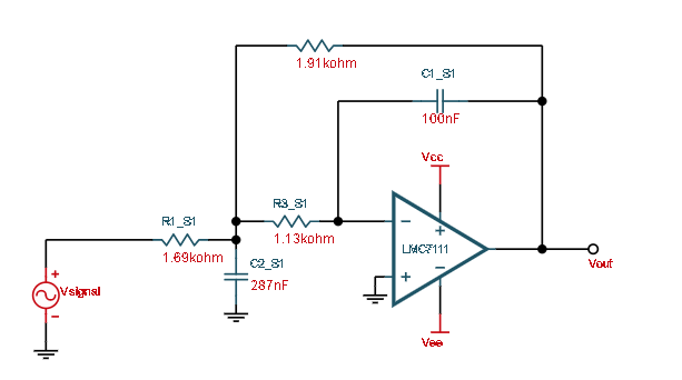
The simulation has more attenuation than expected. I have realized the filter in a PCB with the OPA1632 and I get around -6dB at the passband. I am missing something? Is it a problem of the IC? should I look for another amplifier? How to translate the designs from the Webench filter design tool to a differential amplifier? 

  • Hi Carlos,

    We have forwarded your query to the concerned team. The team will get back to you soon.

    Thanks &Regards,

    Praveen

  • Carlos

    I converted a single-ended lowpass filter to fully differential lowpass filter with MFB topology.

    I managed to get the expected results which the attenuation is -3dB at 500Hz as shown in below figure.

    I spotted from your schematic that you used the default power supply connection, which is in opposite polarity with the OPA1632.

    I changed my connection to match yours which the positive terminal is connected to -5V and negative is connected to 5V.

    I found that the attenuation is -16dB at 500Hz.

    I hope this addresses your issue.

    Regards,

    Alfred

  • Hi Carlos, 

    You've translated the filter properly to the FDA. I've noticed that on the FDA model that the supply voltages are connected inverted (positive supply is at the bottom). I think that is likely your issue. I often get caught off guard by some of the models that have the VS+ pin at the bottom by default. 

    Regards, 

    Jacob 

  • Thank you very much! sorry for the mistake. 

    Best regards