This thread has been locked.

If you have a related question, please click the "Ask a related question" button in the top right corner. The newly created question will be automatically linked to this question.

PMP4259: Unstable in High Loads

Part Number: PMP4259

Dear TI expert, 

I designed a 3 KW PFC boost converter according to PMP4259 reference design based on UCC28070 controller. My design components are attached as a PDF file.

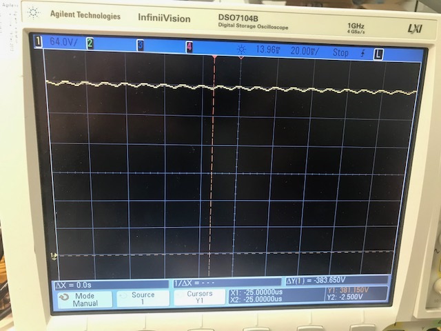
In about 391W output load (383V, 375ohm) all of the required parameters are met as in figures I attached. However, when I connect higher load (600w, 240ohm), the circuit becomes unstable, sinks a lot of current and usually a MOSFET breaks out. I checked all of the gate and CT signals and they seem to be fine. Do you have any idea how I can attack this problem? 

By the way, I have removed current sense PWM ramp circuit and add only 120mV offset to current sense signal. UCC28070_PFC _185-265-400.pdf
  • By the way I am using one PCV-2-274-10L as boost inductor for each channel. 

  • Hello Suheyl,

    I could not figure out schematics of your design., attachment is missing.
    To comment remote I need schematics and bill of material, please provide.

    PMP4259 has been built and tested for universal input, your design is
    highline only, so power capability of PMP4259 will be more than sufficient.

    Just by reading your message - could you please check current sense transformer ?
    You need to avoid saturation under all circumstances.

    Please check RMS rating of your inductors, RMS current will be more than 9Amps;
    yours are limited around 7Amps.

    For further analysis need schematics & BoM, best regards, Bernd

  • Hello Bernd,

    Thank you for your prompt response.

    Actually I was suspicious about the boost inductor as well. But regarding RMS current, can you please share governed equation?

    I use 

    ΔI_L = (V_out • D • (1-D)) / (f_sw • L) = (400 • 0.22 • 0.77) / (37.5K • 235u) = 7.7 A

    and,

    I_in_rms = P_out / (η • V_in )= 650 / (0.93 • 220) = 3.17 A_rms

    so roughly:

    I_L_rms = I_in_rms / 2 + ΔI_L / 2 / 2 = 1.585 + 2.72 = 4.3 A

    So it seems that my calculations are not correct. Maybe I can increase the switching frequency in order to see if it effects the outcomes or not.

    I'm also attaching BoM and schematic which is pretty the same in PMP4259 except the values in the excel sheet (PDF-BoM).

    Thank you again for your time.

    slur217.pdfslur294.pdf

    0640.UCC28070_PFC _185-265-400.pdf

  • Hello Suheyl, quick and dirty estimation:

    if I calculate 200V min. DC input (100Hz ripple !) this results in 50% duty for 400VDC output;
    at 4A output per phase I could see 8.54Arms and up to 13Apk worst case.

    Inductor core needs to w/stand >13A saturation current, true windings stress is in between
    upper 8.54Arms and 5.3Armsat 320V DC in, >7Arms should be a good starting point.
    Can't see the spreadsheet equation.

    And - current ripple seems to be fairly high at 37.5kHz and only 270uH.

    I could see university at your background; may be it's a good idea for high line only and take
    the link below, there you got all the equations - and calculate your power stage once more.

    Best regards, Bernd