This thread has been locked.

If you have a related question, please click the "Ask a related question" button in the top right corner. The newly created question will be automatically linked to this question.

WEBENCH® Tools/BQ25703A: TIDA-01627: Tida-01627: TPS65987DDH cannot use BQ25703A to charge 3 lithium batteries

Part Number: BQ25703A
Other Parts Discussed in Thread: TPS65987D, TPS65981

Tool/software: WEBENCH® Design Tools

Hello team:

Referring to TI Designs: tida-01627 (TPS65987D+BQ25703A)for developing PD charging project, our company has encountered the following situations in the development and needs your help:

1 . At the time of design, tidA-01627 design file is still available on TI's official website, but the design file cannot be found on the official website now. Why is this plan removed from the shelf? Is there any problem?Do we need to revise the plan?

2.The address of BQ25703A in the specification is D6h (1101101_X). The board we designed will read 0x6b address through FTDI tool. Is this the address of BQ25703A?

3.  We use the TPS65981_2_6_7_8 Application Customization 6.1.1 open (.pJT) file When generating burn (.bin) file to Flash, the following image 0x2000,)0x6000 need to be changed?

4.  The default slave address of I2C1 in the project file is 0X6b. Do I need to modify this address? How much do I need to change if I need to?

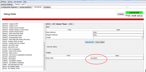
5. At present, TPS65987D and BQ25703A I2C communication is not normal: the battery cannot be charged;We use FTDI tool to read register BQ25703A 0x2E through debug mode, with the value 0x12e03 instead of 0x40h in the specification. Our connection is as follows: PC connects FTDI via USB, I2C2 connects TPS65987D via I2C, and I2C1 connects BQ25703A I2C via TPS65987D.What causes this?

6. We designed to charge 3 lithium batteries, which are not charged at present. The battery voltage is 10.3V, and the measured VSYS voltage of the pin of BQ25703A is 10.5V. What is the voltage of VSYS when the 3 lithium batteries are charged under normal conditions?

  • Hi,

      1. Refer to this E2E post where a similar question has been asked previously

      2. I will double check why you read 6b.

      3,4,5. Create new post with E2E part tag TPS65987D and expert will be able to answer your question

      6. If VBAT < VSYSMIN, then VSYS will be regulated at VSYSMIN, otherwise VSYS will track battery voltage.

  • HI Kedar

         Thank you for your reply.

         1.We refer to the following post of the project file, as follows:

            e2e.ti.com/.../865318

            The full Flash image is generated as follows:     

           d6drpsource.zip

    However, TPS65987D and BQ25703A I2C communication are not normal: the battery cannot be charged. We measured the VBUS voltage as 5V, and measured the VSYS voltage as 9.2V when the battery was pulled out ,and CHRG_OK voltage as 3.3V

    Here are the register values I read using Debug mode

    PD+ quick charge is the first time I use it, and I don't know how to debug it.Can you tell me how I locate  my problem,?

    2.As for the last question 6, where to set VSYSMIN?

      Thanks

  • Hi,

       VSYSMIN is set in register 0x0C. With regards to using the customization tool, I would re-post the question with the TPS part in the title, so the team in charge of TPS65987D can help. The previous post you reference was answered by that team.