This thread has been locked.

If you have a related question, please click the "Ask a related question" button in the top right corner. The newly created question will be automatically linked to this question.

TIDA-00299: Center tap of Pulse Trans.

Part Number: TIDA-00299

Hi,

My customer is considering using DP83822 and refers TIDA-00299 schematic.

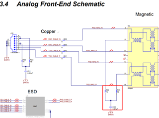
The center tap of the pulse Trans is divided as below on this TIDA;

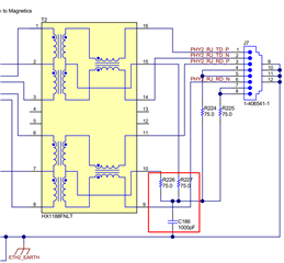
On the other hand, the center tap is connected directly as below on the EVM.

Could you tell me why the center tap is divided on the TIDA schematic?

Best Regards,

Kuramochi

  • Hello Kuramochi,

    I am not sure I understand the question correctly.

    The center tab connection is the Bob Smith connection to terminate the cable.

    If you look at the two center tab connections to the transformer, they are done the same way connecting the 75 Ohm resistor with the 1nF capacitor.

    Since this design is done for 100Mbit two of the Twisted pair cables are floating(not connected to the PHY) and this is why the other two 75 Ohm resistors are used.

    On one design only 1 capacitor is used on the other design two capacitors are used and terminating the Twisted pairs independently.

    PCB wise the split capacitor will allow to keep the noise of the two unused twisted pair cables localized close to the connector without any connection to the other two used Twisted Pair cables or center tap termination

    As as you see on the performance of the EFT testing on the communication port you can argue if this additional component is needed for the DP83822 device, however adding the additional capacitor could improve noise performance even more if layout is done to localize this potential cable noise source.

    Best Regards,

    Kristen

  • Hi Kristen-san,

    Thank you for your help.

    I have an additional question.

    >Since this design is done for 100Mbit two of the Twisted pair cables are floating(not connected to the PHY)

    Could you show this by the schematic?

    I don't see where you designate.

    Best Regards,

    Kuramochi

  • Hello Kuramochi-san,

    If you look at the connector J7 or J12 on the two schematics above which are RJ-45 connectors, you can see that the two times two connector pins have been short circuited on this connector
    Here you can see that one Twisted Pair is on pin 7 and 8, another twisted pair is on 4 and 5.

    Pin 1 2 and 3 5 are the other two twisted pairs of the cable which the 100Mbit Ethernet PHY is using.

    On both schematics you can see that these pairs have been connected and terminated with a 75Ohm and the capacitor(a Bob Smith connection).

    The pin mapping of the RJ-45 connector to the Cat 5e Ethernet cable with 4 twisted Pairs is a predefined specification, which can support both 100 Mbit and 1000Mbit ethernet.

    For details on this please see the see wiki page link under the section 8P8C explaining the cable.

    Best Regards,

    Kristen

  • Hi Kristen-san,

    I understand.

    Do you know why two capacitors(C41&C46) are used on the EVM?

    What is the advantaging of using two capacitors?

    Best Regards,

    Kuramochi

  • Hello Kuramochi-san,

    On the question about 1 or 2 capacitors used on the design, i would say the following.

    PCB wise the split capacitor will allow to keep the noise of the two unused twisted pair cables localized close to the connector without any connection to the other two used Twisted Pair cables or center tap termination

    As as you see on the performance of the EFT testing on the communication port you can argue if this additional component is needed for the DP83822 device, however adding the additional capacitor could improve noise performance even more if layout is done to localize this potential cable noise source away from the two twisted pair cables which are used for data communication.

    Best Regards,

    Kristen