This thread has been locked.

If you have a related question, please click the "Ask a related question" button in the top right corner. The newly created question will be automatically linked to this question.

CC2652P7: Fixed frequency test switch tube state is incorrect

Part Number: CC2652P7
Other Parts Discussed in Thread: CC1352P7

Hi team,

Here's an issue from the customer may need your help:

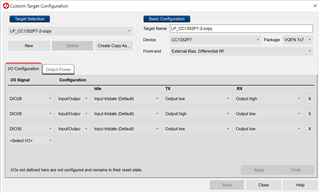
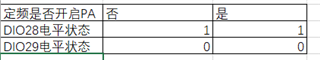
For fixed frequency testing with SmartRF Studio 7 2.24.0, in BLE or 802.15.4 modules, the level states of DIO28 and DIO29 are unchanged regardless of whether the PA is on or off, causing the switch tube to be in an incorrect state.

The truth table for testing whether the PA is turned on is as follows:

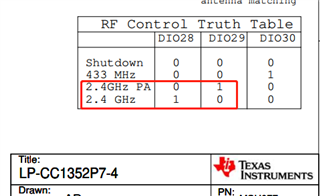
It is inconsistent with the table below:

Could you help check this case? Thanks.

Best Regards,

Cherry

  • Hi Cherry,

    Thank you for letting us know about this issue.  I've replicated the behavior described and found that C:\Program Files (x86)\Texas Instruments\SmartRF Tools\SmartRF Studio 7\config\xml\cc1352p7\targets\target_launchxl-cc1352p7_2_4_ghz_highPA.xml has the incorrect pin settings for DIO28/29.  They should be as such (same as the target_launchxl-cc1352p7-4_highPA.xml version):

        <IoSettings name="RF Switch">
            <IoPin name="DIO28">
                <ControlFunction>Input/Output</ControlFunction>
                <Idle>Input tristate (Default)</Idle>
                <Tx>Output low</Tx>
                <Rx>Output high</Rx>
            </IoPin>
            <IoPin name="DIO29">
                <ControlFunction>Input/Output</ControlFunction>
                <Idle>Input tristate (Default)</Idle>
                <Tx>Output high</Tx>
                <Rx>Output low</Rx>
            </IoPin>
            <IoPin name="DIO30">
                <ControlFunction>Input/Output</ControlFunction>
                <Idle>Input tristate (Default)</Idle>
                <Tx>Output low</Tx>
                <Rx>Output low</Rx>
            </IoPin>
        </IoSettings>

    Please modify target_launchxl-cc1352p7_2_4_ghz_highPA.xml accordingly and restart Smart RF Studio 7 to resolve this issue.  You could also choose to manually change the I/O Configuration inside the Target Configuration "Customize" button, you would need to copy the LP Target Selection with "Create Copy As" before changing the DIO28/29 settings to their proper TX/RX output level and save accordingly.

    I have alerted the corresponding Development Team to address this issue for a future release.

    Regards,
    Ryan