This thread has been locked.

If you have a related question, please click the "Ask a related question" button in the top right corner. The newly created question will be automatically linked to this question.

CC2640R2F: CC2640R2F crashes when the voltage is too low, and cannot wake up when boosting

Part Number: CC2640R2F
Other Parts Discussed in Thread: CC2640,

1. When the problem occurs, the main power supply voltage of Bluetooth is 2.327V;

2. Now this problem can recur stably. After the equipment on the car has a problem, we have recurred this problem on other equipment, which seems to be a common problem.

The method of reproduction is as follows:

• The duplicated logic is to simulate the ignition of the truck battery when the power supply is insufficient. The test circuit diagram is as follows:

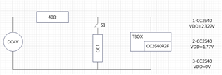
• TBOX is started by Bluetooth. The power supply voltage of TBOX is 4.0V. A 40 ohm resistor is connected in series on the circuit, and a 10 ohm resistor and S1 switch are connected in parallel between the positive and negative poles. S1 switch is off by default.

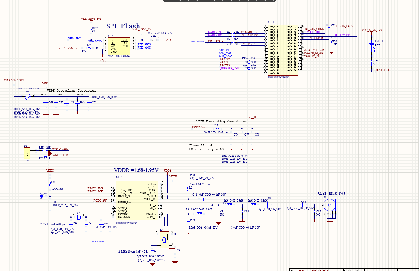
• Step 1: Use the switching power supply to power on TBOX, and disconnect S1. At this time, the main power voltage of CC2640R2F is 2.327V, and the measured voltage between SWD and GND of CC2640 CJtag is 2.327V;

• Step 2: Close S1 switch, measure that the voltage between SWD and GND of CC2640 CJtag is 1.77V, then disconnect S1, measure that the voltage between SWD and GND of CC2640 CJtag is still 1.77V, then quickly close and disconnect S1 switch, about 500-1000 times, the voltage between SWD and GND will still be 0V, and then whatever operation is done later, the voltage output of SWD and GND of CC2640 CJtag will be 0V, It is not enough to increase the power supply voltage. It can only be restored after resetting or powering off.

3. When the voltage output of both the SWD and GND of the CC2640 CJtag is 0V, the crystal oscillator does not start to vibrate, but this problem has been repeated on several devices, and it is uncertain whether it is the crystal oscillator.

When CC2640R2F is started, is there a process of switching from the internal crystal oscillator to the external crystal oscillator? Can we grab the card at which step?

Whether the other three requirements can be realized:

1. Does CC2640R2F support switching from external crystal oscillator to internal crystal oscillator during operation?

2. Does CC2640R2F support the status query of whether the external crystal oscillator operates normally during operation?

3. During the test, we found that the first line after the main increased the delay, which reduced the frequency of problem recurrence. After the modification, it took about 1500 times to reproduce. Can this delay be advanced to the assembly code that started?

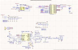
To add, the SDK of CC2640R2F is 4.44.0.10

  • We use the built-in power supply voltage detection register of CC2640R2F to read the power supply voltage. At present, if our setting is lower than 2.8V, CC2640R2F will trigger reset. After 2580 tests yesterday, the problem also occurred.

  • Hi,

    If I understood correctly from your image and description, VDDS falls well below the minimum specification of 1.8V during the truck startup procedure at 0.8V with S1 closed. That should be enough to bring the device to a brownout condition and trigger a System Reset. In this scenario, are you able to read the device's RESETCTL register and see what is the source of the Reset (bit WU_FROM_SD)? Check chapter 6 of the TRM for details. 

    A few aspects of your description that I do not fully understand are: what do you call SWD? Is this the VDDS net? How is it showing 1.77V if the resistive voltage divider can only supply 0.8V to the target? How are you measuring this? If using a simple DMM, there might be voltage spikes that may be confusing the meter and I would use an oscilloscope. 

    The oscilloscope will also be useful to verify the supply rising/falling slew rate. For details, check table 8-27 of the datasheet. 

    At last, keep in mind that noise on the JTAG lines (TMS/TCK pins), can power up the Debug subsystem and which can trigger the device's Halt In Boot (HIB) condition. Check section 5.4 of the TRM for details. 

    Answering your questions:

    1. No.

    2. No. Apart from the aforementioned reset and brownout detector, the device needs a stable oscillator operation to work. 

    3. It is very hard to tell. The boundary conditions of your system are very particular and therefore the correlation between a single line of code and the stability after reset is very difficult to establish. 

    Hope this helps,

    Rafael

  • I have made new progress on the problem that CC2640R2F cannot be ignited. I found that was removed CASE_ AS_ RAM macro After , the program can run normally. It has been running for a long time, and the previous problem has not occurred. As for this function, what might cause this problem.

    This function was enabled because RAM was not enough. I still need this function for online devices. Are there any details that I need to pay attention to

  • In ble/simple_ The example project of peripheral has 3KB of reserved RAM. What is this used for? Can I use it?

    define symbol RESERVED_ RAM_ SIZE = 0x00000C00;

  • Hi,

    The new discovery points to a memory issue with the code you are running, but I am not familiar with the macro CASE_AS_RAM you described. In this case, I will defer to the SW experts. Please share as much information about your code as possible. This will allow us to provide more accurate hints to find the root cause of the problem. 

    The RESERVED_RAM_SIZE is usually required by the BLE stack and should not be modified.

    Regards,

    Rafael

  • Hi,

    Could you please open a new thread explaining the SW issues currently opened?

    This would help to get the SW engineer up and running and ensure other users can leverage the discussion.

    In other words, let's keep the hardware discussion here and have a separate thread for software.

    Appreciate your comprehension.

    Best regards,