This thread has been locked.

If you have a related question, please click the "Ask a related question" button in the top right corner. The newly created question will be automatically linked to this question.

Half duplex UART configuration for CC2340

Other Parts Discussed in Thread: SYSCONFIG, CC2640R2F, CC2340R5, LP-EM-CC2340R5

Can I get an example code for Half duplex UART code?
Currently received as junk characters data when Tx from Teraterm input. 

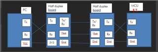
I use half duplex board as input to CC2340.

The connection is PC-UART --> Half duplex boards --> CC2340

semStatus = sem_init(&sem, 0, 0);

if (semStatus != 0)
{
/* Error creating semaphore */
while (1) {}
}

/* Create a UART in CALLBACK read mode */
UART2_Params_init(&uartParams);
uartParams.readMode = UART2_Mode_CALLBACK;
uartParams.readCallback = callbackFxn;
uartParams.baudRate = 3000000;


uart = UART2_open(CONFIG_UART2_0, &uartParams);

if (uart == NULL)
{
/* UART2_open() failed */
while (1) {}
}

/* Turn on user LED to indicate successful initialization */
GPIO_write(CONFIG_GPIO_LED_0, CONFIG_GPIO_LED_ON);

/* Pass NULL for bytesWritten since it's not used in this example */
UART2_write(uart, echoPrompt, sizeof(echoPrompt), NULL);

/* Loop forever echoing */
while (1)
{
numBytesRead = 0;

/* Pass NULL for bytesRead since it's not used in this example */
status = UART2_read(uart, &input, sizeof(input), NULL);


printf("status result =%d\n",status);

if (status != UART2_STATUS_SUCCESS)
{
/* UART2_read() failed */
while (1) {}
}

//SysCtlDelay(SysCtlClockGet() / 3); // delay 1 second

/* Do not write until read callback executes */
sem_wait(&sem);
if (numBytesRead > 0)
{
status = UART2_write(uart, &input, sizeof(input), NULL);

if (status != UART2_STATUS_SUCCESS)
{
/* UART2_write() failed */
while (1) {}
}
}

  • Hey Natu,

    Thanks for posting on E2E. I've assigned your post to a colleague to comment on.

    P.S. - I hope you don't mind, I cleaned up the thread by reformatting the code inserted by hitting Insert>Code and pasting in your code. I also took the liberty of moving the thread to the right forum. Slight smile

  • Hi Natu,

    To confirm, will you be implementing both TX and RX communication through the half duplex scheme? If not, then I would suggest setting up the UART for TX or RX only in SysConfig. If both TX and RX are necessary, then I would suggest implementing a full duplex if possible as this will allow simultaneous TX and RX activity to occur. The default examples included in the SDK are implemented in full duplex and the UART2 library uses full duplex.

    Best Regards,

    Jan

  • Thanks for your reply. I will be implementing both TX and RX communication through the half duplex scheme. The objective is to achieve half duplex. I verified with full duplex and it works good, but with half duplex the data received is not as expected, there is framing error and data received are junk characters. 

  • Hi Jan,

    In run time can I configure the UART direction to Send Only when its UART read and set direction to Receive Only when trying to UART write?
    In SysConfig as you suggested I see this option UART21.dataDirection = "Receive Only"; or UART21.dataDirection = "Send Only"; 
    But I need to configure this in runtime. Is there any way?

  • Upto 1.5MHz I can send and receive the data in Half Duplex mode. But when set to 3MHz, the RX is not correct. I need a way to set "Send Only" during TX and when RX, I need to disable the UART TX and set back UART TX when TX

  • I found related post for CC2640R2F  RTOS/CC2640R2F: Disabling UART TX while UART RX is active - Bluetooth forum - Bluetooth®︎ - TI E2E support forums
    But I need similar settings to CC2340 chip. 

    PINCC26XX_setMux(object->hPin, hwAttrs->txPin, IOC_PORT_GPIO)
    PINCC26XX_setMux(object->hPin, hwAttrs->txPin, IOC_PORT_MCU_UART0_TX)


    Can suggest on this?

  • Hi,

    I am glad to see you have had some success with getting the half-duplex scheme to work. With regards to the PINCC26XX_setMux() function, I believe the equivalent should be GPIO_setMux(). I would suggest looking into the UART2 Dynamic Pin Switching section of the CC23xx User's Guide for an example on how to use this function with regards to UART.

    Best Regards,

    Jan

  • Hi Jan,
    I couldn't get any CC23xx User's Guide from TI website. Have only Technical-Reference-Manual which doesn't have the info which you suggested.
    Thanks

  • Hello,

    The CC23xx User's Guide is now included in the latest CC23xx SDK release present in Secure Resources. Can you confirm which SDK version you are using? The 6.30 SDK version should contain the documentation I mentioned within the "docs" folder.

    Best Regards,

    Jan

  • Currently using 6.20 SDK version. I tried with 6.30 SDK version also the results are same for the half duplex at 3Mbps. The "docs" folder which you mentioned for 6.30 SDK version doesn't have any info on UART2 Dynamic Pin Switching.

  • Hi,

    The UART2 Dynamic Pin Switching can be found within Developing with SDK CC23xx chapter inside the Development Resources section:

    Best Regards,

    Jan

  • Is the documentation confidential? I cannot find from the My Secure Software sharing.

  • Hi Natu,

    The documentation should be present inside the docs folder of the CC23xx SDK directory. The CC23xx SDK is not available to general public and is downloaded through My Secure Sharing. The docs are contained within the SDK itself. Is that section of the User's Guide not present in your SDK installation?

    Best Regards,

    Jan

  • No, under docs-> simplelink_mcu_sdk -> Users_Guide   don't have the section for  UART2 Dynamic Pin Switching. Can you please provide this document access?

  • Hi Jan,

    Found the section under quickstart-guide/quickstart-intro-cc23xx.html. But the UART switching didn't work for Half duplex

  • Hi Natu,

    I am glad to hear you were able to find it! The information in that page is for a full duplex UART, but I think it may be helpful in implementing the single duplex in order to reconfigure the UART pin during runtime. You will need to do some modifications to that code segment, but I think it may be a good starting point.

    Best Regards,

    Jan

  • I tried these settings but I can only get to receive the data but unable to transmit back

  • Need help again on the transmitting back when receive the data.

  • Hi,

    I would try referencing the UART2switchPins() function shown below:

    static void UART2switchPins(uint8_t oldTxPin, uint8_t oldRxPin, uint8_t newTxPin, uint8_t newRxPin, uint8_t newTxMux, uint8_t newRxMux)
    {
       //Settings old UART pins to internal MUX
       GPIO_setMux(oldTxPin, GPIO_MUX_GPIO_INTERNAL);
       GPIO_setMux(oldRxPin, GPIO_MUX_GPIO_INTERNAL);
    
       // Configuring new UART pins for UART
       GPIO_setConfig(newTxPin, GPIO_CFG_OUTPUT_INTERNAL | GPIO_CFG_OUT_STR_MED | GPIO_CFG_OUT_HIGH);
       GPIO_setConfig(newRxPin, GPIO_CFG_INPUT_INTERNAL | GPIO_CFG_IN_INT_NONE | GPIO_CFG_PULL_DOWN_INTERNAL);
    
       // Configuring new UART pins with new MUX
       GPIO_setMux(newTxPin, newTxMux);
       GPIO_setMux(newRxPin, newRxMux);
    
       return;
    }

    I think if you modify the function such that it changes a single pin between TX and RX as needed, then it may work. I would try first setting it to RX and then setting it to TX. You may need to clear the buffer between changing the pin between TX and RX. The rest of the example shown in that section of the User's Guide shows how to switch the pins dynamically and how to clear the buffer.

    Can you try this and let me know if you run into any issues?

    Best Regards,

    Jan

  • Hi Jan,

    Below is the software setting for Half duplex, can receive but cannot transmit back. In Sys config I have set UART data direction as "Send Only" if configure as "Send and Receive" cannot receive or transmit the data. 

    #include <stdint.h>
    #include <stddef.h>

    /* POSIX Header files */
    #include <semaphore.h>

    /* Driver Header files */
    #include <ti/drivers/GPIO.h>
    #include <ti/drivers/UART2.h>

    /* Driver configuration */
    #include "ti_drivers_config.h"

    static sem_t sem;
    static volatile size_t numBytesRead;


    static void UART2switchTxPins(uint8_t oldRxPin, uint8_t newTxPin, uint8_t newTxMux)
    {
    //Settings old UART pins to internal MUX
    GPIO_setMux(oldRxPin, GPIO_MUX_GPIO_INTERNAL);
    GPIO_setConfig(oldRxPin,1);

    // Configuring new UART pins for UART
    GPIO_setConfig(newTxPin, GPIO_CFG_OUTPUT_INTERNAL | GPIO_CFG_OUT_STR_MED | GPIO_CFG_OUT_HIGH);

    // Configuring new UART pins with new MUX
    GPIO_setMux(newTxPin, newTxMux);

    return;
    }

    static void UART2switchRxPins(uint8_t oldTxPin, uint8_t newRxPin, uint8_t newRxMux)
    {
    //Settings old UART pins to internal MUX
    GPIO_setMux(oldTxPin, GPIO_MUX_GPIO_INTERNAL);
    GPIO_setConfig(oldTxPin,0);

    // Configuring new UART pins for UART
    GPIO_setConfig(newRxPin, GPIO_CFG_INPUT_INTERNAL | GPIO_CFG_IN_INT_NONE | GPIO_CFG_PULL_DOWN_INTERNAL);

    // Configuring new UART pins with new MUX
    GPIO_setMux(newRxPin, newRxMux);

    return;
    }

    /*
    * ======== mainThread ========
    */
    void *mainThread(void *arg0)
    {
    char input;
    const char echoPrompt[] = "Echoing characters:\r\n";
    UART2_Handle uart;
    UART2_Params uartParams;
    int32_t semStatus;
    uint32_t status = UART2_STATUS_SUCCESS;

    /* Call driver init functions */
    GPIO_init();

    /* Configure the LED pin */
    GPIO_setConfig(CONFIG_GPIO_LED_0, GPIO_CFG_OUT_STD | GPIO_CFG_OUT_LOW);

    /* Create semaphore */
    semStatus = sem_init(&sem, 0, 0);

    if (semStatus != 0)
    {
    /* Error creating semaphore */
    while (1) {}
    }

    /* Create a UART in CALLBACK read mode */
    UART2_Params_init(&uartParams);
    uartParams.readMode = UART2_Mode_NONBLOCKING;
    uartParams.readCallback = callbackFxn;
    uartParams.baudRate = 3000000;

    uart = UART2_open(CONFIG_UART2_0, &uartParams);

    if (uart == NULL)
    {
    /* UART2_open() failed */
    while (1) {}
    }

    /* Turn on user LED to indicate successful initialization */
    GPIO_write(CONFIG_GPIO_LED_0, CONFIG_GPIO_LED_ON);

    /* Loop forever echoing */
    while (1)
    {
    numBytesRead = 0;

    /* Pass NULL for bytesRead since it's not used in this example */
    status = UART2_read(uart, &input, 1, NULL);

    if (status != UART2_STATUS_SUCCESS)
    {
    /* UART2_read() failed */
    while (1) {}
    }
    UART2_flushRx(uart);

    /* Do not write until read callback executes */
    sem_wait(&sem);
    sleep(10);
    UART2_close(uart);
    UART2_open(CONFIG_UART2_0, &uartParams);
    UART2switchTxPins(22,20,2);

    status = UART2_write(uart, &input, 1, NULL);
    if (status != UART2_STATUS_SUCCESS)
    {
    /* UART2_write() failed */
    while (1) {}
    }
    UART2_flushRx(uart);

    UART2_close(uart);
    UART2_open(CONFIG_UART2_0, &uartParams);
    UART2switchRxPins(20,22,2);
    }
    }

  • Hi,

    I would further modify what you have to be something along the following. You would need to change between the TX and RX configuration depending on when you want to send and transmit data on the half duplex line. Can you see if something along the lines of the following code segment is helpful?

        
        UART2_flushRx(uart);
        
        UART2_close(uart);
        UART2_open(CONFIG_UART2_0, &uartParams);
        
        //Changing from TX to RX
        GPIO_setConfig(uartPin, GPIO_CFG_INPUT_INTERNAL | GPIO_CFG_IN_INT_NONE | GPIO_CFG_PULL_DOWN_INTERNAL);
        
        
        ...
        
        UART2_flushRx(uart);
        
        UART2_close(uart);
        UART2_open(CONFIG_UART2_0, &uartParams);
        
        //Changing from RX to TX
        GPIO_setConfig(uartPin, GPIO_CFG_OUTPUT_INTERNAL | GPIO_CFG_OUT_STR_MED | GPIO_CFG_OUT_HIGH);
        

    Best Regards,

    Jan


  • Hi Jan,

    I tried the above config but didn't work. The connection for my setup is as mentioned in this image. I need to still use Tx and Rx pins but I need to switch dynamically at run time. 

  • Hi Natu,

    Based on your diagram and your reply, it seems the CC23XX device will be using TX and RX which will change dynamically during runtime? If that is the case, then the solution presented in User's Guide section should be helpful here. Am I understanding correctly?

    Best Regards,

    Jan

  • Hi Jan,

    Another way I tried is to disable Tx pin when receiving data, but the TX pin is not disabled by the below setting. Can I know the correct setting to set TX pin to High Impedance?

    GPIO_setConfig(CONFIG_GPIO_UART2_0_TX, GPIO_CFG_INPUT_INTERNAL | GPIO_CFG_IN_INT_NONE | GPIO_CFG_PULL_DOWN_INTERNAL);
    GPIO_setMux(CONFIG_GPIO_UART2_0_TX, GPIO_MUX_PORTCFG_PFUNC2);


  • Hi Natu,

    Are you closing and reopening  the UART driver before running those lines? The driver should be closed and re-opened in order to clear all the buffers. Afterwards, I would also flush the rx buffer to be safe.

    Best Regards,

    Jan

  • Hi Jan,

    Yes I'm currently trying to receive the data from host. So, I initialized the UART, opened, flushed the RX buffer, set GPIO config as above and read the data. So, still unable to receive data.

  • Hi Natu,

    Can you clarify how you are flushing the RX buffer? Are you using UART2_close() followed by a UART2_open()? This is how it is done in the UART2 Dynamic Pin Switching Example section of the User's Guide. I am able to run that sample code successfully to switch the UART pin configuration during runtime. As mentioned previously, I believe we should be able to use that sample code as a base to implement the desired functionality.

    Best Regards,

    Jan

  • Yes I have tried UART2_close() and UART2_open(). These are the below changes.

    #ifdef ENABLED_RX
            bytesRead = 0;
            while (bytesRead == 0)
            {
                status = UART2_read(uart, &input, 1, &bytesRead);
    
                if (status != UART2_STATUS_SUCCESS)
                {
                    /* UART2_read() failed */
                    while (1) {}
                }
                UART2_close(CONFIG_UART2_0);
                uart = UART2_open(CONFIG_UART2_0, &uartParams);
                prepareTx();
                UART2_rxDisable( uart );
            }
    #endif
    
    #ifdef ENABLED_TX
            bytesWritten = 0;
            while (bytesWritten == 0)
            {
                status = UART2_write(uart, &echoPrompt, sizeof(echoPrompt), &bytesWritten);
    
                if (status != UART2_STATUS_SUCCESS)
                {
                    /* UART2_write() failed */
                    while (1) {}
                }
                UART2_flushRx(uart);
                UART2_close(CONFIG_UART2_0);
                uart = UART2_open(CONFIG_UART2_0, &uartParams);
                prepareRx();
                UART2_rxEnable( uart );
            }
    #endif

  • Hi Natu,

    When the device is initialized can you share what state the UART is initialized to? Are you initializing the UART2 module to do RX or TX first? Before performing any switching, does the UART work as expected? In other words, if the UART is initialized first to RX, does the RX work well before the switch is done?

    Best Regards,

    Jan

  • Yes I have initialized UART before switching. I have initialized to RX first. Yes after initialized, RX works but it doesn't send back after switch to TX


    UART2_Params_init(&uartParams);
    uartParams.baudRate = 3000000U;
    
    uart = UART2_open(CONFIG_UART2_0, &uartParams);
    
    if (uart == NULL)
    {
        /* UART2_open() failed */
        while (1) {}
    }
    prepareRx();
    UART2_rxEnable( uart );

  • The TX and RX functions are working individually but when dynamically switch it doesn't work. Here is the full code

    /*
     *  ======== uart2echo.c ========
     */
    #include <stdint.h>
    #include <stddef.h>
    
    /* Driver Header files */
    #include <ti/drivers/GPIO.h>
    #include <ti/drivers/UART2.h>
    
    /* Driver configuration */
    #include "ti_drivers_config.h"
    #define ENABLED_RX
    #define ENABLED_TX
    
    static void prepareRx(void)
    {
       // GPIO_setConfig(CONFIG_GPIO_UART2_0_TX, GPIO_CFG_OUTPUT_INTERNAL | GPIO_CFG_IN_INT_NONE | GPIO_CFG_OUT_OD_NOPULL);
        GPIO_setConfig(CONFIG_GPIO_UART2_0_TX, GPIO_CFG_OUTPUT_INTERNAL | GPIO_CFG_OUT_STR_MED | GPIO_CFG_OUT_OD_NOPULL);
        GPIO_setConfig(CONFIG_GPIO_UART2_0_RX, GPIO_CFG_INPUT_INTERNAL | GPIO_CFG_OUT_STR_MED | GPIO_CFG_OUT_HIGH);
        GPIO_setMux(CONFIG_GPIO_UART2_0_TX, 2);
        GPIO_setMux(CONFIG_GPIO_UART2_0_RX, 2);
    }
    
    static void prepareTx(void)
    {
        GPIO_setConfig(CONFIG_GPIO_UART2_0_TX, GPIO_CFG_OUTPUT_INTERNAL | GPIO_CFG_OUT_STR_MED | GPIO_CFG_OUT_HIGH);
        GPIO_setConfig(CONFIG_GPIO_UART2_0_RX, GPIO_CFG_INPUT_INTERNAL | GPIO_CFG_IN_INT_NONE | GPIO_CFG_OUT_OD_NOPULL);
        GPIO_setMux(CONFIG_GPIO_UART2_0_RX, 2);
        GPIO_setMux(CONFIG_GPIO_UART2_0_TX, 2);
    }
    /*
     *  ======== mainThread ========
     */
    void *mainThread(void *arg0)
    {
        char input;
        const uint8_t echoPrompt = 0x35;
        UART2_Handle uart;
        UART2_Params uartParams;
        size_t bytesRead;
        size_t bytesWritten = 0;
        uint32_t status     = UART2_STATUS_SUCCESS;
    
        /* Call driver init functions */
        GPIO_init();
    
        /* Configure the LED pin */
        GPIO_setConfig(CONFIG_GPIO_LED_0, GPIO_CFG_OUT_STD | GPIO_CFG_OUT_LOW);
    
        /* Create a UART where the default read and write mode is BLOCKING */
        UART2_Params_init(&uartParams);
        //uartParams.readMode = UART2_Mode_BLOCKING;
        //uartParams.writeMode = UART2_Mode_BLOCKING;
        uartParams.baudRate = 3000000U;
    
        uart = UART2_open(CONFIG_UART2_0, &uartParams);
    
        if (uart == NULL)
        {
            /* UART2_open() failed */
            while (1) {}
        }
    
        /* Turn on user LED to indicate successful initialization */
        GPIO_write(CONFIG_GPIO_LED_0, CONFIG_GPIO_LED_ON);
    
    #if 1 //def ENABLED_RX
        prepareRx();
        UART2_rxEnable( uart );
    #endif
    
    
        /* Loop forever echoing */
        while (1)
        {
    #ifdef ENABLED_RX
            bytesRead = 0;
            while (bytesRead == 0)
            {
                status = UART2_read(uart, &input, 1, &bytesRead);
    
                if (status != UART2_STATUS_SUCCESS)
                {
                    /* UART2_read() failed */
                    while (1) {}
                }
                UART2_close(CONFIG_UART2_0);
                uart = UART2_open(CONFIG_UART2_0, &uartParams);
                prepareTx();
                UART2_rxDisable( uart );
            }
    #endif
    
    #ifdef ENABLED_TX
            bytesWritten = 0;
            while (bytesWritten == 0)
            {
                status = UART2_write(uart, &echoPrompt, sizeof(echoPrompt), &bytesWritten);
    
                if (status != UART2_STATUS_SUCCESS)
                {
                    /* UART2_write() failed */
                    while (1) {}
                }
                UART2_flushRx(uart);
                UART2_close(CONFIG_UART2_0);
                uart = UART2_open(CONFIG_UART2_0, &uartParams);
                prepareRx();
                UART2_rxEnable( uart );
            }
    #endif
        }
    }


  • Hi Natu,

    Can you specify which pin you are using? If you want to do TX and RX in a single pin, then the pin selected must support both UART TX and UART RX. The datasheet states that DIO20 is able to implement both UART TX and UART RX, so I would suggest trying that one if possible.

    Best Regards,

    Jan

  • Tx and Rx are not used in a single pin. I disable Rx pin when transmitting and keep Tx as active and disable Tx pin and keep Rx as active while Receiving.

    Tx is pin 20 and Rx pin is 21

  • Provide me your working code so I can configure similar way.

  • Hi Natu,

    My sincerest apologies, I misunderstood your configuration. I was under the impression that we were only using a single pin for both TX and RX in half-duplex mode on the CC2340. If the goal is to have a single TX pin & a single separate RX pin on the CC2340R5, and disables RX when TX is active (and vice versa). Then this should be possible without having to reconfigure the pins during runtime.

    I have taken the uart2callback example and made a few modifications to implement this. The modified uart2callback.c code can be found below:

    /*
     * Copyright (c) 2022, Texas Instruments Incorporated
     * All rights reserved.
     *
     * Redistribution and use in source and binary forms, with or without
     * modification, are permitted provided that the following conditions
     * are met:
     *
     * *  Redistributions of source code must retain the above copyright
     *    notice, this list of conditions and the following disclaimer.
     *
     * *  Redistributions in binary form must reproduce the above copyright
     *    notice, this list of conditions and the following disclaimer in the
     *    documentation and/or other materials provided with the distribution.
     *
     * *  Neither the name of Texas Instruments Incorporated nor the names of
     *    its contributors may be used to endorse or promote products derived
     *    from this software without specific prior written permission.
     *
     * THIS SOFTWARE IS PROVIDED BY THE COPYRIGHT HOLDERS AND CONTRIBUTORS "AS IS"
     * AND ANY EXPRESS OR IMPLIED WARRANTIES, INCLUDING, BUT NOT LIMITED TO,
     * THE IMPLIED WARRANTIES OF MERCHANTABILITY AND FITNESS FOR A PARTICULAR
     * PURPOSE ARE DISCLAIMED. IN NO EVENT SHALL THE COPYRIGHT OWNER OR
     * CONTRIBUTORS BE LIABLE FOR ANY DIRECT, INDIRECT, INCIDENTAL, SPECIAL,
     * EXEMPLARY, OR CONSEQUENTIAL DAMAGES (INCLUDING, BUT NOT LIMITED TO,
     * PROCUREMENT OF SUBSTITUTE GOODS OR SERVICES; LOSS OF USE, DATA, OR PROFITS;
     * OR BUSINESS INTERRUPTION) HOWEVER CAUSED AND ON ANY THEORY OF LIABILITY,
     * WHETHER IN CONTRACT, STRICT LIABILITY, OR TORT (INCLUDING NEGLIGENCE OR
     * OTHERWISE) ARISING IN ANY WAY OUT OF THE USE OF THIS SOFTWARE,
     * EVEN IF ADVISED OF THE POSSIBILITY OF SUCH DAMAGE.
     */
    
    /*
     *  ======== uart2callback.c ========
     */
    #include <stdint.h>
    #include <stddef.h>
    
    /* POSIX Header files */
    #include <semaphore.h>
    
    /* Driver Header files */
    #include <ti/drivers/GPIO.h>
    #include <ti/drivers/UART2.h>
    
    /* Driver configuration */
    #include "ti_drivers_config.h"
    
    static sem_t sem;
    static volatile size_t numBytesRead;
    UART2_Handle uart;
    
    #define TX_MODE     0
    #define RX_MODE     1
    
    uint8_t currentMode = RX_MODE;
    const char echoPrompt[] = "Transmit!\r\n";
    
    /*
     *  ======== callbackFxn ========
     */
    void callbackFxn(UART2_Handle handle, void *buffer, size_t count, void *userArg, int_fast16_t status)
    {
        if (status != UART2_STATUS_SUCCESS)
        {
            /* RX error occured in UART2_read() */
            while (1) {}
        }
    
        numBytesRead = count;
        sem_post(&sem);
    }
    
    // Left button press callback
    // Toggle between transfer modse
    void gpioButtonFxn0(uint_least8_t index)
    {
        if(currentMode == RX_MODE)
        {
            GPIO_write(CONFIG_GPIO_LED_1, CONFIG_GPIO_LED_ON);
            UART2_rxDisable(uart);
            currentMode = TX_MODE;
    
        }
        else
        {
            GPIO_write(CONFIG_GPIO_LED_1, CONFIG_GPIO_LED_OFF);
            UART2_rxEnable(uart);
            currentMode = RX_MODE;
        }
    }
    
    
    void gpioButtonFxn1(uint_least8_t index)
    {
        if(currentMode == TX_MODE)
        {
            /* Pass NULL for bytesWritten since it's not used in this example */
            UART2_write(uart, echoPrompt, sizeof(echoPrompt), NULL);
        }
    }
    
    
    /*
     *  ======== mainThread ========
     */
    void *mainThread(void *arg0)
    {
        char input;
    
        UART2_Params uartParams;
        int32_t semStatus;
        uint32_t status = UART2_STATUS_SUCCESS;
    
        /* Call driver init functions */
        GPIO_init();
    
        /* Configure the LED and button pins */
        GPIO_setConfig(CONFIG_GPIO_LED_0, GPIO_CFG_OUT_STD | GPIO_CFG_OUT_LOW);
        GPIO_setConfig(CONFIG_GPIO_LED_1, GPIO_CFG_OUT_STD | GPIO_CFG_OUT_LOW);
        GPIO_setConfig(CONFIG_GPIO_BUTTON_0, GPIO_CFG_IN_PU | GPIO_CFG_IN_INT_FALLING);
    
    
        /* Install Button callback */
        GPIO_setCallback(CONFIG_GPIO_BUTTON_0, gpioButtonFxn0);
    
        /* Enable interrupts */
        GPIO_enableInt(CONFIG_GPIO_BUTTON_0);
    
        /*
         *  If more than one input pin is available for your device, interrupts
         *  will be enabled on CONFIG_GPIO_BUTTON1.
         */
        if (CONFIG_GPIO_BUTTON_0 != CONFIG_GPIO_BUTTON_1)
        {
            /* Configure BUTTON1 pin */
            GPIO_setConfig(CONFIG_GPIO_BUTTON_1, GPIO_CFG_IN_PU | GPIO_CFG_IN_INT_FALLING);
    
            /* Install Button callback */
            GPIO_setCallback(CONFIG_GPIO_BUTTON_1, gpioButtonFxn1);
            GPIO_enableInt(CONFIG_GPIO_BUTTON_1);
        }
    
    
        /* Create semaphore */
        semStatus = sem_init(&sem, 0, 0);
    
        if (semStatus != 0)
        {
            /* Error creating semaphore */
            while (1) {}
        }
    
        /* Create a UART in CALLBACK read mode */
        UART2_Params_init(&uartParams);
        uartParams.readMode     = UART2_Mode_CALLBACK;
        uartParams.readCallback = callbackFxn;
        uartParams.baudRate     = 115200;
    
        uart = UART2_open(CONFIG_UART2_0, &uartParams);
    
        if (uart == NULL)
        {
            /* UART2_open() failed */
            while (1) {}
        }
    
    
        /* Turn on user LED to indicate successful initialization */
        GPIO_write(CONFIG_GPIO_LED_0, CONFIG_GPIO_LED_ON);
    
    
        // Perform initial write
        UART2_write(uart, echoPrompt, sizeof(echoPrompt), NULL);
    
        // Perform initial read
        status = UART2_read(uart, &input, 1, NULL);
    
        // Start in TX Mode
        currentMode = TX_MODE;
        GPIO_write(CONFIG_GPIO_LED_1, CONFIG_GPIO_LED_ON);
        UART2_rxDisable(uart);
    
    
        /* Loop forever echoing */
        while (1)
        {
            numBytesRead = 0;
    
            /* Pass NULL for bytesRead since it's not used in this example */
            status = UART2_read(uart, &input, 1, NULL);
    
            if (currentMode == RX_MODE && status != UART2_STATUS_SUCCESS && status != UART2_STATUS_EINUSE)
            {
                /* UART2_read() failed */
                while (1) {}
            }
    
            // Toggle LED for each byte received
            while(numBytesRead > 0)
            {
                numBytesRead--;
                GPIO_toggle(CONFIG_GPIO_LED_0);
            }
        }
    }

    In SysConfig, I added the second LED and the two GPIO buttons. In this example, the device is able to toggle between TX only and RX only by pressing the button on the LaunchPad. When in RX mode, if any UART data is read, then one of the LEDs will toggle for each byte read. In TX mode, no data will be read and a UART transmission will sent whenever the right button is pressed.

    This logic was implemented using the UART2_rxDisable() and UART2_rxEnable() functions.

    For my project I used DIO20 for TX and DIO22 for RX. These are the pins used by default which are connected to the XDS110.

    In the project, I used a global status variable to never allow any writes to take place unless the status is set to TX_MODE. While in TX_MODE, the rxDisable function is used to disallow the circular buffer from being filled by incoming UART transmissions. In RX_MODE, the rxEnable function is used to resume data collection on the circular buffer.

    Please let me know if you have any issues with the provided code or have any questions about this.

    Best Regards,

    Jan

  • Hi,

    No, this doesn't help to resolve the issue. Even if both the Tx and Rx pins are separate on TI side, the half duplex board has connected the Tx and Rx pins connected to single pin. Does this impact the setting on TI side? So, I was suggesting to disable RX(set to open drain) when TX is active (and vice versa).

    The example code which you provided doesn't switch in runtime. It just sends "Transmit!" once and keep reading forever.

  • Hi Natu,

    My apologies for any confusion.  In the provided code, pressing the left button toggles the state of the UART. When the device is in TX_MODE, the UART2_rxDisable() function is called which prevents the RX ring buffer from collecting data from the RX pin. This means that whenever UART2_read() is called, no data should be read even if there is activity on the pin. In this state, logic has been added that allows a UART2_write() call to be executed if the right button is pressed (which sends "Transmit!").

    When the device is in RX_MODE, the UART2_rxEnable() function is called which allows data to be collected in the ring buffer which can then be read when calling UART2_read(). In this mode, when pressing the right button, logic has been added that prevents the UART2_write() call from being made.

    However, I have modified the example to disable the pin as you have mentioned. Can you verify if this example implements your desired functionality?

    /*
     * Copyright (c) 2020, Texas Instruments Incorporated
     * All rights reserved.
     *
     * Redistribution and use in source and binary forms, with or without
     * modification, are permitted provided that the following conditions
     * are met:
     *
     * *  Redistributions of source code must retain the above copyright
     *    notice, this list of conditions and the following disclaimer.
     *
     * *  Redistributions in binary form must reproduce the above copyright
     *    notice, this list of conditions and the following disclaimer in the
     *    documentation and/or other materials provided with the distribution.
     *
     * *  Neither the name of Texas Instruments Incorporated nor the names of
     *    its contributors may be used to endorse or promote products derived
     *    from this software without specific prior written permission.
     *
     * THIS SOFTWARE IS PROVIDED BY THE COPYRIGHT HOLDERS AND CONTRIBUTORS "AS IS"
     * AND ANY EXPRESS OR IMPLIED WARRANTIES, INCLUDING, BUT NOT LIMITED TO,
     * THE IMPLIED WARRANTIES OF MERCHANTABILITY AND FITNESS FOR A PARTICULAR
     * PURPOSE ARE DISCLAIMED. IN NO EVENT SHALL THE COPYRIGHT OWNER OR
     * CONTRIBUTORS BE LIABLE FOR ANY DIRECT, INDIRECT, INCIDENTAL, SPECIAL,
     * EXEMPLARY, OR CONSEQUENTIAL DAMAGES (INCLUDING, BUT NOT LIMITED TO,
     * PROCUREMENT OF SUBSTITUTE GOODS OR SERVICES; LOSS OF USE, DATA, OR PROFITS;
     * OR BUSINESS INTERRUPTION) HOWEVER CAUSED AND ON ANY THEORY OF LIABILITY,
     * WHETHER IN CONTRACT, STRICT LIABILITY, OR TORT (INCLUDING NEGLIGENCE OR
     * OTHERWISE) ARISING IN ANY WAY OUT OF THE USE OF THIS SOFTWARE,
     * EVEN IF ADVISED OF THE POSSIBILITY OF SUCH DAMAGE.
     */
    
    /*
     *  ======== uart2callback.c ========
     */
    #include <stdint.h>
    #include <stddef.h>
    
    /* POSIX Header files */
    #include <semaphore.h>
    
    /* Driver Header files */
    #include <ti/drivers/GPIO.h>
    #include <ti/drivers/UART2.h>
    
    /* Driver configuration */
    #include "ti_drivers_config.h"
    
    static sem_t sem;
    static volatile size_t numBytesRead;
    UART2_Handle uart;
    UART2_Params uartParams;
    
    #define TX_MODE     0
    #define RX_MODE     1
    
    uint8_t currentMode = RX_MODE;
    uint8_t changeToRx = 0;
    uint8_t changeToTx = 0;
    const char echoPrompt[] = "Transmit!\r\n";
    
    /*
     *  ======== callbackFxn ========
     */
    void callbackFxn(UART2_Handle handle, void *buffer, size_t count, void *userArg, int_fast16_t status)
    {
        if (status != UART2_STATUS_SUCCESS && status != UART2_STATUS_ECANCELLED)
        {
            /* RX error occured in UART2_read() */
            while (1) {}
        }
    
        numBytesRead = count;
        sem_post(&sem);
    }
    
    // Left button press callback
    // Toggle between transfer modse
    void gpioButtonFxn0(uint_least8_t index)
    {
        if(currentMode == RX_MODE)
        {
            GPIO_write(CONFIG_GPIO_LED_1, CONFIG_GPIO_LED_ON);
    
            changeToTx = 1;
            currentMode = TX_MODE;
    
        }
        else
        {
            GPIO_write(CONFIG_GPIO_LED_1, CONFIG_GPIO_LED_OFF);
    
            changeToRx = 1;
            currentMode = RX_MODE;
        }
    }
    
    
    void gpioButtonFxn1(uint_least8_t index)
    {
        UART2_write(uart, echoPrompt, sizeof(echoPrompt), NULL);
    }
    
    
    /*
     *  ======== mainThread ========
     */
    void *mainThread(void *arg0)
    {
        char input;
    
    
        int32_t semStatus;
        uint32_t status = UART2_STATUS_SUCCESS;
    
        /* Call driver init functions */
        GPIO_init();
    
        /* Configure the LED and button pins */
        GPIO_setConfig(CONFIG_GPIO_LED_0, GPIO_CFG_OUT_STD | GPIO_CFG_OUT_LOW);
        GPIO_setConfig(CONFIG_GPIO_LED_1, GPIO_CFG_OUT_STD | GPIO_CFG_OUT_LOW);
        GPIO_setConfig(CONFIG_GPIO_BUTTON_0, GPIO_CFG_IN_PU | GPIO_CFG_IN_INT_FALLING);
    
    
        /* Install Button callback */
        GPIO_setCallback(CONFIG_GPIO_BUTTON_0, gpioButtonFxn0);
    
        /* Enable interrupts */
        GPIO_enableInt(CONFIG_GPIO_BUTTON_0);
    
        /*
         *  If more than one input pin is available for your device, interrupts
         *  will be enabled on CONFIG_GPIO_BUTTON1.
         */
        if (CONFIG_GPIO_BUTTON_0 != CONFIG_GPIO_BUTTON_1)
        {
            /* Configure BUTTON1 pin */
            GPIO_setConfig(CONFIG_GPIO_BUTTON_1, GPIO_CFG_IN_PU | GPIO_CFG_IN_INT_FALLING);
    
            /* Install Button callback */
            GPIO_setCallback(CONFIG_GPIO_BUTTON_1, gpioButtonFxn1);
            GPIO_enableInt(CONFIG_GPIO_BUTTON_1);
        }
    
    
        /* Create semaphore */
        semStatus = sem_init(&sem, 0, 0);
    
        if (semStatus != 0)
        {
            /* Error creating semaphore */
            while (1) {}
        }
    
        /* Create a UART in CALLBACK read mode */
        UART2_Params_init(&uartParams);
        uartParams.readMode     = UART2_Mode_CALLBACK;
        uartParams.readCallback = callbackFxn;
        uartParams.baudRate     = 115200;
    
        uart = UART2_open(CONFIG_UART2_0, &uartParams);
    
        // Disable RX pin
        GPIO_setMux(22, GPIO_MUX_GPIO_INTERNAL);
    
        // Enable TX pin
        GPIO_setConfig(20, GPIO_CFG_OUTPUT_INTERNAL | GPIO_CFG_OUT_STR_MED | GPIO_CFG_OUT_HIGH);  // Configure TX
        GPIO_setMux(20, 2);
    
        if (uart == NULL)
        {
            /* UART2_open() failed */
            while (1) {}
        }
    
    
        /* Turn on user LED to indicate successful initialization */
        GPIO_write(CONFIG_GPIO_LED_0, CONFIG_GPIO_LED_ON);
    
        // Perform initial write
        UART2_write(uart, echoPrompt, sizeof(echoPrompt), NULL);
    
        // Start in TX Mode
        currentMode = TX_MODE;
        GPIO_write(CONFIG_GPIO_LED_1, CONFIG_GPIO_LED_ON);
    
    
        /* Loop forever echoing */
        while (1)
        {
            numBytesRead = 0;
    
            /* Pass NULL for bytesRead since it's not used in this example */
            status = UART2_read(uart, &input, 1, NULL);
    
            if (currentMode == RX_MODE && status != UART2_STATUS_SUCCESS && status != UART2_STATUS_EINUSE)
            {
                /* UART2_read() failed */
                while (1) {}
            }
    
            // Toggle LED for each byte received
            while(numBytesRead > 0)
            {
                numBytesRead--;
                GPIO_toggle(CONFIG_GPIO_LED_0);
            }
    
            if(changeToRx == 1)
            {
    
                changeToRx = 0;
                // Close and restart UART to clear buffers
                UART2_readCancel(uart);
                UART2_close(uart);
                UART2_open(CONFIG_UART2_0, &uartParams);
    
                // Disable TX pin
                GPIO_setMux(20, GPIO_MUX_GPIO_INTERNAL);
    
                // Enable RX Pin
                GPIO_setConfig(22, GPIO_CFG_INPUT_INTERNAL | GPIO_CFG_IN_INT_NONE | GPIO_CFG_PULL_DOWN_INTERNAL); // Configure RX
                GPIO_setMux(22, 2);
    
                UART2_flushRx(uart);
            }
    
            if(changeToTx == 1)
            {
                changeToTx = 0;
                // Close and restart UART to clear buffers
                UART2_readCancel(uart);
                UART2_close(uart);
                UART2_open(CONFIG_UART2_0, &uartParams);
    
                // Disable RX pin
                GPIO_setMux(22, GPIO_MUX_GPIO_INTERNAL);
    
                // Enable TX pin
                GPIO_setConfig(20, GPIO_CFG_OUTPUT_INTERNAL | GPIO_CFG_OUT_STR_MED | GPIO_CFG_OUT_HIGH);  // Configure TX
                GPIO_setMux(20, 2);


                // Disable RX
                UART2_flushRx(uart);
            }
        }
    }
    

    Best Regards,

    Jan

  • Hi Jan,

    The code below eventually works half duplex way without connected to full setup. But when connect as a complete setup as mentioned in above block diagram, it just Reads and Write one time and just stop there. Is there any flaw in the below code.

    Note: While disabling the pin setting to GPIO_MUX_GPIO_INTERNAL doesn't work so I had to set to GPIO_CFG_OUT_OD_NOPULL.

    /*
     * Copyright (c) 2020, Texas Instruments Incorporated
     * All rights reserved.
     *
     * Redistribution and use in source and binary forms, with or without
     * modification, are permitted provided that the following conditions
     * are met:
     *
     * *  Redistributions of source code must retain the above copyright
     *    notice, this list of conditions and the following disclaimer.
     *
     * *  Redistributions in binary form must reproduce the above copyright
     *    notice, this list of conditions and the following disclaimer in the
     *    documentation and/or other materials provided with the distribution.
     *
     * *  Neither the name of Texas Instruments Incorporated nor the names of
     *    its contributors may be used to endorse or promote products derived
     *    from this software without specific prior written permission.
     *
     * THIS SOFTWARE IS PROVIDED BY THE COPYRIGHT HOLDERS AND CONTRIBUTORS "AS IS"
     * AND ANY EXPRESS OR IMPLIED WARRANTIES, INCLUDING, BUT NOT LIMITED TO,
     * THE IMPLIED WARRANTIES OF MERCHANTABILITY AND FITNESS FOR A PARTICULAR
     * PURPOSE ARE DISCLAIMED. IN NO EVENT SHALL THE COPYRIGHT OWNER OR
     * CONTRIBUTORS BE LIABLE FOR ANY DIRECT, INDIRECT, INCIDENTAL, SPECIAL,
     * EXEMPLARY, OR CONSEQUENTIAL DAMAGES (INCLUDING, BUT NOT LIMITED TO,
     * PROCUREMENT OF SUBSTITUTE GOODS OR SERVICES; LOSS OF USE, DATA, OR PROFITS;
     * OR BUSINESS INTERRUPTION) HOWEVER CAUSED AND ON ANY THEORY OF LIABILITY,
     * WHETHER IN CONTRACT, STRICT LIABILITY, OR TORT (INCLUDING NEGLIGENCE OR
     * OTHERWISE) ARISING IN ANY WAY OUT OF THE USE OF THIS SOFTWARE,
     * EVEN IF ADVISED OF THE POSSIBILITY OF SUCH DAMAGE.
     */
    
    /*
     *  ======== uart2echo.c ========
     */
    #include <stdint.h>
    #include <stdio.h>
    #include <stddef.h>
    
    /* Driver Header files */
    #include <ti/drivers/GPIO.h>
    #include <ti/drivers/UART2.h>
    
    /* Driver configuration */
    #include "ti_drivers_config.h"
    
    #define ENABLED_TX
    #define ENABLED_RX
    
    static void prepareRx(void)
    {
        GPIO_setConfig(CONFIG_GPIO_UART2_0_TX, GPIO_CFG_OUT_OD_NOPULL);
        GPIO_setConfig(22, GPIO_CFG_INPUT_INTERNAL | GPIO_CFG_IN_INT_NONE | GPIO_CFG_PULL_DOWN_INTERNAL); // Configure RX
        GPIO_setMux(CONFIG_GPIO_UART2_0_TX, 2);
        GPIO_setMux(CONFIG_GPIO_UART2_0_RX, 2);
    }
    
    static void prepareTx(void)
    {
        GPIO_setConfig(CONFIG_GPIO_UART2_0_RX, GPIO_CFG_OUT_OD_NOPULL);
        GPIO_setConfig(20, GPIO_CFG_OUTPUT_INTERNAL | GPIO_CFG_OUT_STR_MED | GPIO_CFG_OUT_HIGH);  // Configure TX
        GPIO_setMux(CONFIG_GPIO_UART2_0_TX, 2);
        GPIO_setMux(CONFIG_GPIO_UART2_0_RX, 2);
    }
    /*
     *  ======== mainThread ========
     */
    void *mainThread(void *arg0)
    {
        char input;
        const uint8_t echoPrompt = 0x35;
        UART2_Handle uart;
        UART2_Params uartParams;
        size_t bytesRead;
        size_t bytesWritten = 0;
        uint32_t status     = UART2_STATUS_SUCCESS;
    
        /* Call driver init functions */
        GPIO_init();
    
        /* Configure the LED pin */
        GPIO_setConfig(CONFIG_GPIO_LED_0, GPIO_CFG_OUT_STD | GPIO_CFG_OUT_LOW);
    
        /* Create a UART where the default read and write mode is BLOCKING */
        UART2_Params_init(&uartParams);
        uartParams.baudRate = 3000000;
        //uartParams.readMode = UART2_Mode_BLOCKING;
        //uartParams.writeMode = UART2_Mode_BLOCKING;
    
        uart = UART2_open(CONFIG_UART2_0, &uartParams);
    
        if (uart == NULL)
        {
            /* UART2_open() failed */
            while (1) {}
        }
    
        /* Turn on user LED to indicate successful initialization */
        GPIO_write(CONFIG_GPIO_LED_0, CONFIG_GPIO_LED_ON);
        //UART2_write(uart, &echoPrompt, sizeof(echoPrompt), &bytesWritten);
        printf("TI Init\n");
    
        /* Loop forever echoing */
        while ( 1 )
        {
    #ifdef ENABLED_RX
            bytesRead = 0;
            //while (bytesRead == 0)
            {
                UART2_readCancel(uart);
                UART2_close(uart);
                UART2_open(CONFIG_UART2_0, &uartParams);
                prepareRx();
                UART2_flushRx(uart);
                UART2_rxEnable( uart );
                status = UART2_read(uart, &input, sizeof(input), &bytesRead);
                printf("TI Read UART = %c %d\n",input, status);
    
                if (status != UART2_STATUS_SUCCESS)
                {
                    /* UART2_read() failed */
                    while (1) {}
                }
            }
    #endif
    
    #ifdef ENABLED_TX
            bytesWritten = 0;
            //while (bytesWritten == 0)
            {
                UART2_readCancel(uart);
                UART2_close(uart);
                UART2_open(CONFIG_UART2_0, &uartParams);
                prepareTx();
                UART2_flushRx(uart);
                UART2_rxDisable( uart );
                status = UART2_write(uart, &echoPrompt, sizeof(echoPrompt), &bytesWritten);
                printf("TI Write UART = %c %d\n",echoPrompt, status);
    
                if (status != UART2_STATUS_SUCCESS)
                {
                    /* UART2_write() failed */
                    while (1) {}
                }
            }
    #endif
        }
    }


  • Hi Natu,

    I did some testing on an LP-EM-CC2340R5 with DIO20 and DIO22 shorted and I believe I have found a configuration that is able to do TX and RX in the half-duplex mode you have described. When disabling a pin, you must set the GPIO config to GPIO_CFG_NO_DIR_INTERNAL | GPIO_CFG_PULL_NONE_INTERNAL and the mux must be set to GPIO_MUX_GPIO_INTERNAL. Essentially the following lines must be called when a pin is to be disabled in your setup:

    // Disable TX pin
    GPIO_setConfig(20, GPIO_CFG_NO_DIR_INTERNAL | GPIO_CFG_PULL_NONE_INTERNAL);
    GPIO_setMux(20, GPIO_MUX_GPIO_INTERNAL);
    
    
    ...
    
    
    // Disable RX pin
    GPIO_setConfig(22, GPIO_CFG_NO_DIR_INTERNAL | GPIO_CFG_PULL_NONE_INTERNAL);
    GPIO_setMux(22, GPIO_MUX_GPIO_INTERNAL);

    My entire application code can be found here:

    /*
     * Copyright (c) 2020, Texas Instruments Incorporated
     * All rights reserved.
     *
     * Redistribution and use in source and binary forms, with or without
     * modification, are permitted provided that the following conditions
     * are met:
     *
     * *  Redistributions of source code must retain the above copyright
     *    notice, this list of conditions and the following disclaimer.
     *
     * *  Redistributions in binary form must reproduce the above copyright
     *    notice, this list of conditions and the following disclaimer in the
     *    documentation and/or other materials provided with the distribution.
     *
     * *  Neither the name of Texas Instruments Incorporated nor the names of
     *    its contributors may be used to endorse or promote products derived
     *    from this software without specific prior written permission.
     *
     * THIS SOFTWARE IS PROVIDED BY THE COPYRIGHT HOLDERS AND CONTRIBUTORS "AS IS"
     * AND ANY EXPRESS OR IMPLIED WARRANTIES, INCLUDING, BUT NOT LIMITED TO,
     * THE IMPLIED WARRANTIES OF MERCHANTABILITY AND FITNESS FOR A PARTICULAR
     * PURPOSE ARE DISCLAIMED. IN NO EVENT SHALL THE COPYRIGHT OWNER OR
     * CONTRIBUTORS BE LIABLE FOR ANY DIRECT, INDIRECT, INCIDENTAL, SPECIAL,
     * EXEMPLARY, OR CONSEQUENTIAL DAMAGES (INCLUDING, BUT NOT LIMITED TO,
     * PROCUREMENT OF SUBSTITUTE GOODS OR SERVICES; LOSS OF USE, DATA, OR PROFITS;
     * OR BUSINESS INTERRUPTION) HOWEVER CAUSED AND ON ANY THEORY OF LIABILITY,
     * WHETHER IN CONTRACT, STRICT LIABILITY, OR TORT (INCLUDING NEGLIGENCE OR
     * OTHERWISE) ARISING IN ANY WAY OUT OF THE USE OF THIS SOFTWARE,
     * EVEN IF ADVISED OF THE POSSIBILITY OF SUCH DAMAGE.
     */
    
    /*
     *  ======== uart2callback.c ========
     */
    #include <stdint.h>
    #include <stddef.h>
    
    /* POSIX Header files */
    #include <semaphore.h>
    
    /* Driver Header files */
    #include <ti/drivers/GPIO.h>
    #include <ti/drivers/UART2.h>
    
    /* Driver configuration */
    #include "ti_drivers_config.h"
    
    static sem_t sem;
    static volatile size_t numBytesRead;
    UART2_Handle uart;
    UART2_Params uartParams;
    
    #define TX_MODE     0
    #define RX_MODE     1
    
    uint8_t currentMode = RX_MODE;
    uint8_t changeToRx = 0;
    uint8_t changeToTx = 0;
    const char echoPrompt[] = "Transmit!\r\n";
    
    /*
     *  ======== callbackFxn ========
     */
    void callbackFxn(UART2_Handle handle, void *buffer, size_t count, void *userArg, int_fast16_t status)
    {
        if (status != UART2_STATUS_SUCCESS && status != UART2_STATUS_ECANCELLED)
        {
            /* RX error occured in UART2_read() */
            while (1) {}
        }
    
        numBytesRead = count;
        sem_post(&sem);
    }
    
    // Left button press callback
    // Toggle between transfer modse
    void gpioButtonFxn0(uint_least8_t index)
    {
        if(currentMode == RX_MODE)
        {
            GPIO_write(CONFIG_GPIO_LED_1, CONFIG_GPIO_LED_ON);
    
            changeToTx = 1;
            currentMode = TX_MODE;
    
        }
        else
        {
            GPIO_write(CONFIG_GPIO_LED_1, CONFIG_GPIO_LED_OFF);
    
            changeToRx = 1;
            currentMode = RX_MODE;
        }
    }
    
    
    void gpioButtonFxn1(uint_least8_t index)
    {
        UART2_write(uart, echoPrompt, sizeof(echoPrompt), NULL);
    }
    
    
    /*
     *  ======== mainThread ========
     */
    void *mainThread(void *arg0)
    {
        char input;
    
    
        int32_t semStatus;
        uint32_t status = UART2_STATUS_SUCCESS;
    
        /* Call driver init functions */
        GPIO_init();
    
        /* Configure the LED and button pins */
        GPIO_setConfig(CONFIG_GPIO_LED_0, GPIO_CFG_OUT_STD | GPIO_CFG_OUT_LOW);
        GPIO_setConfig(CONFIG_GPIO_LED_1, GPIO_CFG_OUT_STD | GPIO_CFG_OUT_LOW);
        GPIO_setConfig(CONFIG_GPIO_BUTTON_0, GPIO_CFG_IN_PU | GPIO_CFG_IN_INT_FALLING);
    
    
        /* Install Button callback */
        GPIO_setCallback(CONFIG_GPIO_BUTTON_0, gpioButtonFxn0);
    
        /* Enable interrupts */
        GPIO_enableInt(CONFIG_GPIO_BUTTON_0);
    
        /*
         *  If more than one input pin is available for your device, interrupts
         *  will be enabled on CONFIG_GPIO_BUTTON1.
         */
        if (CONFIG_GPIO_BUTTON_0 != CONFIG_GPIO_BUTTON_1)
        {
            /* Configure BUTTON1 pin */
            GPIO_setConfig(CONFIG_GPIO_BUTTON_1, GPIO_CFG_IN_PU | GPIO_CFG_IN_INT_FALLING);
    
            /* Install Button callback */
            GPIO_setCallback(CONFIG_GPIO_BUTTON_1, gpioButtonFxn1);
            GPIO_enableInt(CONFIG_GPIO_BUTTON_1);
        }
    
    
        /* Create semaphore */
        semStatus = sem_init(&sem, 0, 0);
    
        if (semStatus != 0)
        {
            /* Error creating semaphore */
            while (1) {}
        }
    
        /* Create a UART in CALLBACK read mode */
        UART2_Params_init(&uartParams);
        uartParams.readMode     = UART2_Mode_CALLBACK;
        uartParams.readCallback = callbackFxn;
        uartParams.baudRate     = 115200;
    
        uart = UART2_open(CONFIG_UART2_0, &uartParams);
    
        // Disable RX pin
        GPIO_setConfig(22,GPIO_CFG_NO_DIR_INTERNAL | GPIO_CFG_PULL_NONE_INTERNAL);
        GPIO_setMux(22, GPIO_MUX_GPIO_INTERNAL);
    
        // Enable TX pin
        GPIO_setConfig(20, GPIO_CFG_OUTPUT_INTERNAL | GPIO_CFG_OUT_STR_MED | GPIO_CFG_OUT_HIGH);  // Configure TX
        GPIO_setMux(20, 2);
    
        UART2_rxDisable(uart);
    
        if (uart == NULL)
        {
            /* UART2_open() failed */
            while (1) {}
        }
    
    
        /* Turn on user LED to indicate successful initialization */
        GPIO_write(CONFIG_GPIO_LED_0, CONFIG_GPIO_LED_ON);
    
        // Perform initial write
        UART2_write(uart, echoPrompt, sizeof(echoPrompt), NULL);
    
        // Start in TX Mode
        currentMode = TX_MODE;
        GPIO_write(CONFIG_GPIO_LED_1, CONFIG_GPIO_LED_ON);
    
    
        /* Loop forever echoing */
        while (1)
        {
            numBytesRead = 0;
    
            /* Pass NULL for bytesRead since it's not used in this example */
            status = UART2_read(uart, &input, 1, NULL);
    
            if (currentMode == RX_MODE && status != UART2_STATUS_SUCCESS && status != UART2_STATUS_EINUSE)
            {
                /* UART2_read() failed */
                while (1) {}
            }
    
            // Toggle LED for each byte received
            while(numBytesRead > 0)
            {
                numBytesRead--;
                GPIO_toggle(CONFIG_GPIO_LED_0);
            }
    
            if(changeToRx == 1)
            {
    
                changeToRx = 0;
                // Close and restart UART to clear buffers
                UART2_readCancel(uart);
                UART2_close(uart);
                UART2_open(CONFIG_UART2_0, &uartParams);
    
                // Disable TX pin
                GPIO_setConfig(20, GPIO_CFG_NO_DIR_INTERNAL | GPIO_CFG_PULL_NONE_INTERNAL);
                GPIO_setMux(20, GPIO_MUX_GPIO_INTERNAL);
    
                // Enable RX Pin
                GPIO_setConfig(22, GPIO_CFG_INPUT_INTERNAL | GPIO_CFG_IN_INT_NONE | GPIO_CFG_PULL_DOWN_INTERNAL); // Configure RX
                GPIO_setMux(22, 2);
    
                UART2_rxEnable(uart);
                UART2_flushRx(uart);
            }
    
            if(changeToTx == 1)
            {
                changeToTx = 0;
                // Close and restart UART to clear buffers
                UART2_readCancel(uart);
                UART2_close(uart);
                UART2_open(CONFIG_UART2_0, &uartParams);
    
                // Disable RX pin
                GPIO_setConfig(22, GPIO_CFG_NO_DIR_INTERNAL | GPIO_CFG_PULL_NONE_INTERNAL);
                GPIO_setMux(22, GPIO_MUX_GPIO_INTERNAL);
    
                // Enable TX pin
                GPIO_setConfig(20, GPIO_CFG_OUTPUT_INTERNAL | GPIO_CFG_OUT_STR_MED | GPIO_CFG_OUT_HIGH);  // Configure TX
                GPIO_setMux(20, 2);


                // Disable RX
                UART2_rxDisable(uart);
                UART2_flushRx(uart);
            }
        }
    }
    

    On my setup, I was able to successfully send and receive data while having a jumper over the DIO20 and DIO22 pins on the LaunchPad. Can you try using the GPIO parameters I mentioned earlier on your side? If you have issues with the given parameters, then could you try using the application code provided to ensure we can see the same behavior using the same firmware?

    Best Regards,

    Jan

  • My previous code works for the switching. Can I know what is the minimum interval for the continuous switching for Half Duplex?

  • Hi Natu,

    This is likely something that would need to be found experimentally. I would suggest creating a project that switches between the pins with a given interval. Afterwards, I would suggest varying the intervals and testing for stability.

    Best Regards,

    Jan

  • Hi Jan,

    I tried to experiment and switching from Read to Write is taking around 1.4ms(with delay of 1ns added). After UART2_rxDisable, how long does it need to set the UART to UART2_rxEnable.

    I am using nanosleep as the delay function, can I know if there is any alternative. With this I found that the delay is found to be ~1.4ms, but the expectation is nano second delay.

        struct timespec tim;
        tim.tv_sec = 0;
        tim.tv_nsec = 1;
        
        prepareRx();
        UART2_rxEnable( uart );
        UART2_flushRx(uart);
        UART2_read(uart, rxCpyBuffer, sizeof(rxCpyBuffer), NULL); // start another read
        nanosleep(&tim, NULL);

  • Hi Natu,

    My sincerest apologies for the delay. To measure the amount of time it takes for a piece of code to execute, I would recommend setting a GPIO to high at the start of code segment and then setting it to low at the end of the code segment. Using a oscilloscope, you can then precisely measure the amount of time between the start and the end point. Can you try this and see if you still get the 1.4ms?

    Best Regards,

    Jan 

  • The timing of 1.4ms may be due to the system clock config. Can I know how to set the clock config to High frequency for UART use?

  • Hi Natu,

    To clarify, are you seeing the 1.4ms elapsed time when using the oscilloscope as well? The device has a main system clock of 48 MHz and an internal low-frequency system clock of 32kHz. 

    Best Regards,

    Jan

  • I measured using Logic analyzer.

  • Hi Natu,

    Got it. Is the board running in debug mode while the measurements are made or is the board running normally?

    Best Regards,

    Jan

  • The board is not running in debug mode. Its running normally.

  • Hi Natu,

    Got it. That does seem like strange behavior. Could you share the project you are using for your testing so we can replicate this behavior on our side?

    Best Regards,

    Jan

  • nanosleep() causes the delay to be around 1.4ms. Replaced it with vTaskDelay() and reduced the delay to microsecond. Can I know the reason for this variation?