


Other Parts Discussed in Thread: CC2650, OPT3001, FDC2214
Hi,
I designed a Devpack board that can communicate through I2C to CC2650STK. The devpack has been verified that data can be obtained by using Sensor Controller Studio.
I try to modify the example project i2ctmp007_CC2650STK_TI for I2C communication between the devpack and cc2650.
The current problem is that both SensorI2C_writeReg() and SensorI2C_writeReg() cannot successfully write and read data respectively.
These two functions are taken from SensorI2C.c in the example project sensortag_cc2650stk_app. And they have been verified to write and read data from the onboard OPT3001.
The code is shown below.
#define Devpack_FDC2214_ADDR (0x54) has been added to the Board.h file. So Devpack_FDC2214_ADDR should be available as i2c address.
/*
 * Copyright (c) 2016, Texas Instruments Incorporated
 * All rights reserved.
 *
 * Redistribution and use in source and binary forms, with or without
 * modification, are permitted provided that the following conditions
 * are met:
 *
 * *  Redistributions of source code must retain the above copyright
 *    notice, this list of conditions and the following disclaimer.
 *
 * *  Redistributions in binary form must reproduce the above copyright
 *    notice, this list of conditions and the following disclaimer in the
 *    documentation and/or other materials provided with the distribution.
 *
 * *  Neither the name of Texas Instruments Incorporated nor the names of
 *    its contributors may be used to endorse or promote products derived
 *    from this software without specific prior written permission.
 *
 * THIS SOFTWARE IS PROVIDED BY THE COPYRIGHT HOLDERS AND CONTRIBUTORS "AS IS"
 * AND ANY EXPRESS OR IMPLIED WARRANTIES, INCLUDING, BUT NOT LIMITED TO,
 * THE IMPLIED WARRANTIES OF MERCHANTABILITY AND FITNESS FOR A PARTICULAR
 * PURPOSE ARE DISCLAIMED. IN NO EVENT SHALL THE COPYRIGHT OWNER OR
 * CONTRIBUTORS BE LIABLE FOR ANY DIRECT, INDIRECT, INCIDENTAL, SPECIAL,
 * EXEMPLARY, OR CONSEQUENTIAL DAMAGES (INCLUDING, BUT NOT LIMITED TO,
 * PROCUREMENT OF SUBSTITUTE GOODS OR SERVICES; LOSS OF USE, DATA, OR PROFITS;
 * OR BUSINESS INTERRUPTION) HOWEVER CAUSED AND ON ANY THEORY OF LIABILITY,
 * WHETHER IN CONTRACT, STRICT LIABILITY, OR TORT (INCLUDING NEGLIGENCE OR
 * OTHERWISE) ARISING IN ANY WAY OUT OF THE USE OF THIS SOFTWARE,
 * EVEN IF ADVISED OF THE POSSIBILITY OF SUCH DAMAGE.
 */

/*
 *    ======== i2ctmp007.c ========
 */

/* XDCtools Header files */
#include <xdc/std.h>
#include <xdc/runtime/System.h>

/* BIOS Header files */
#include <ti/sysbios/BIOS.h>
#include <ti/sysbios/knl/Clock.h>
#include <ti/sysbios/knl/Task.h>
#include <ti/drivers/i2c/I2CCC26XX.h>

/* TI-RTOS Header files */
#include <ti/drivers/PIN.h>
#include <ti/drivers/I2C.h>

/* Example/Board Header files */
#include "Board.h"

//#include "math.h"

#define TASKSTACKSIZE       1024

/* Conversion macros */
#define HI_UINT16(a)     (((a) >> 8) & 0xFF)
#define LO_UINT16(a)     ((a) & 0xFF)
#define SWAP(v)          ((LO_UINT16(v) << 8) | HI_UINT16(v))

/* FDC Register addresses */
// config
#define REG_CLOCK_DIVIDER_CH0           0x14
#define REG_CLOCK_DIVIDER_CH1           0x15
#define REG_CLOCK_DIVIDER_CH2           0x16

#define REG_CONFIG                      0x1A

#define REG_DRIVE_CURRENT_CH0           0x1E
#define REG_DRIVE_CURRENT_CH1           0x1F
#define REG_DRIVE_CURRENT_CH2           0x20

#define REG_ERROR_CONFIG                0x19
#define REG_MUX_CONFIG                  0x1B

#define REG_RCOUNT_CH0                  0x08
#define REG_RCOUNT_CH1                  0x09
#define REG_RCOUNT_CH2                  0x0A

#define REG_SETTLECOUNT_CH0             0x10
#define REG_SETTLECOUNT_CH1             0x11
#define REG_SETTLECOUNT_CH2             0x12

// result
#define REG_DATA_CH0_LSB                0x01
#define REG_DATA_CH0_MSB                0x00

//ID
#define REG_MANUFACTURER_ID             0x7E
#define REG_DEVICE_ID                   0x7F

/* FDC Register values (little endian) */
// config
#define CLOCK_DIVIDER_CH0               0x2002
#define CLOCK_DIVIDER_CH1               0x2002
#define CLOCK_DIVIDER_CH2               0x2002

#define CONFIG_ENABLE                   0x1601  // active mode
#define CONFIG_DISABLE                  0x2801  // sleep mode

#define DRIVE_CURRENT_CH0               0x7C00
#define DRIVE_CURRENT_CH1               0x7C00
#define DRIVE_CURRENT_CH2               0x7C00

#define ERROR_CONFIG                    0x0000
#define MUX_CONFIG                      0xC20D

#define RCOUNT_CH0                      0x8329
#define RCOUNT_CH1                      0x8329
#define RCOUNT_CH2                      0x8329

#define SETTLECOUNT_CH0                 0x000A
#define SETTLECOUNT_CH1                 0x000A
#define SETTLECOUNT_CH2                 0x000A

// ID
#define MANUFACTURER_ID                 0x5449
#define DEVICE_ID                       0x3055

/* Register length */
#define REGISTER_LENGTH                 2

/* Sensor data size */
#define DATA_SIZE                       4


/* local variables */
static uint8_t buf[DATA_SIZE];
static uint16_t val;
//static uint16_t rawData;

/* I2C driver interface */
static I2C_Handle i2cHandle;
static I2C_Params i2cParams;

/* Module state */
static volatile uint8_t interface;
static volatile uint8_t slaveAddr = Devpack_FDC2214_ADDR;   // I2C address of FDC2214 = 0x54
static uint8_t buffer[32];

/* Global memory storage for a PIN_Config table */
static PIN_State ledPinState;

/*
 * Application LED pin configuration table:
 *   - All LEDs board LEDs are off.
 */
PIN_Config ledPinTable[] = {
    Board_LED1 | PIN_GPIO_OUTPUT_EN | PIN_GPIO_LOW | PIN_PUSHPULL | PIN_DRVSTR_MAX,
    Board_LED2 | PIN_GPIO_OUTPUT_EN | PIN_GPIO_LOW | PIN_PUSHPULL | PIN_DRVSTR_MAX,
    PIN_TERMINATE
};


/* -----------------------------------------------------------------------------
*  Public Functions
* ------------------------------------------------------------------------------
*/
/*******************************************************************************
* @fn          SensorI2C_write
*
* @brief       Burst write to an I2C device
*
* @param       data - pointer to data buffer
* @param       len - number of bytes to write
*
* @return      true if success
*/
bool SensorI2C_write(uint8_t *data, uint8_t len)
{
    I2C_Transaction masterTransaction;

    masterTransaction.writeCount   = len;
    masterTransaction.writeBuf     = data;
    masterTransaction.readCount    = 0;
    masterTransaction.readBuf      = NULL;
    masterTransaction.slaveAddress = slaveAddr;

    return I2C_transfer(i2cHandle, &masterTransaction) == TRUE;
}

/*******************************************************************************
* @fn          SensorI2C_writeSingle
*
* @brief       Single byte write to an I2C device
*
* @param       data - byte to write
*
* @return      true if success
*/
bool SensorI2C_writeSingle(uint8_t data)
{
    uint8_t d;

    d = data;

    return SensorI2C_write(&d, 1);
}

/*******************************************************************************
* @fn          SensorI2C_read
*
* @brief       Burst read from an I2C device
*
* @param       data - pointer to data buffer
* @param       len - number of bytes to write
*
* @return      true if success
*/
bool SensorI2C_read(uint8_t *data, uint8_t len)
{
    I2C_Transaction masterTransaction;

    masterTransaction.writeCount = 0;
    masterTransaction.writeBuf = NULL;
    masterTransaction.readCount = len;
    masterTransaction.readBuf = data;
    masterTransaction.slaveAddress = slaveAddr;

    return I2C_transfer(i2cHandle, &masterTransaction) == TRUE;
}

/*******************************************************************************
* @fn          SensorI2C_writeRead
*
* @brief       Burst write/read from an I2C device
*
* @param       wdata - pointer to write data buffer
* @param       wlen - number of bytes to write
* @param       rdata - pointer to read data buffer
* @param       rlen - number of bytes to read
*
* @return      true if success
*/
bool SensorI2C_writeRead(uint8_t *wdata, uint8_t wlen, uint8_t *rdata, uint8_t rlen)
{
    I2C_Transaction masterTransaction;

    masterTransaction.writeCount = wlen;
    masterTransaction.writeBuf = wdata;
    masterTransaction.readCount = rlen;
    masterTransaction.readBuf = rdata;
    masterTransaction.slaveAddress = slaveAddr;

    return I2C_transfer(i2cHandle, &masterTransaction) == TRUE;
}

/*******************************************************************************
* @fn          SensorI2C_readReg
*
* @brief       This function implements the I2C protocol to read from a sensor.
*              The sensor must be selected before this routine is called.
*
* @param       addr - which register to read
* @param       pBuf - pointer to buffer to place data
* @param       nBytes - number of bytes to read
*
* @return      TRUE if the required number of bytes are received
******************************************************************************/
bool SensorI2C_readReg(uint8_t addr, uint8_t *pBuf, uint8_t nBytes)
{
    return SensorI2C_writeRead(&addr,1,pBuf,nBytes);
}

/*******************************************************************************
* @fn          SensorI2C_writeReg
* @brief       This function implements the I2C protocol to write to a sensor.
*              The sensor must be selected before this routine is called.
*
* @param       addr - which register to write
* @param       pBuf - pointer to buffer containing data to be written
* @param       nBytes - number of bytes to write
*
* @return      TRUE if successful write
*/
bool SensorI2C_writeReg(uint8_t addr, uint8_t *pBuf, uint8_t nBytes)
{
    uint8_t i;
    uint8_t *p = buffer;

    /* Copy address and data to local buffer for burst write */
    *p++ = addr;
    for (i = 0; i < nBytes; i++)
    {
        *p++ = *pBuf++;
    }
    nBytes++;

    /* Send data */
    return SensorI2C_write(buffer,nBytes);
}


Task_Struct task0Struct;
Char task0Stack[TASKSTACKSIZE];

/*
 *  ======== echoFxn ========
 *  Task for this function is created statically. See the project's .cfg file.
 */
Void taskFxn(UArg arg0, UArg arg1)
{
    bool            success;
    unsigned int    i;
    uint8_t         rxBuffer[DATA_SIZE];
    uint16_t        rawMSB, rawLSB;

    /* Create I2C for usage */
    I2C_Params_init(&i2cParams);
    i2cParams.bitRate = I2C_400kHz;
    i2cHandle = I2C_open(Board_I2C_TMP, &i2cParams);
    if (i2cHandle == NULL) {
        System_abort("Error Initializing I2C\n");
    }
    else {
        System_printf("I2C Initialized!\n");
    }


    // FDC initialization
    val = CLOCK_DIVIDER_CH0;
    val = SWAP(val);

    SensorI2C_writeReg(REG_CLOCK_DIVIDER_CH0, (uint8_t *)&val, REGISTER_LENGTH);

    val = DRIVE_CURRENT_CH0;
    val = SWAP(val);
    SensorI2C_writeReg(REG_DRIVE_CURRENT_CH0, (uint8_t *)&val, REGISTER_LENGTH);

    val = SETTLECOUNT_CH0;
    val = SWAP(val);
    SensorI2C_writeReg(REG_SETTLECOUNT_CH0, (uint8_t *)&val, REGISTER_LENGTH);

    val = RCOUNT_CH0;
    val = SWAP(val);
    SensorI2C_writeReg(REG_RCOUNT_CH0, (uint8_t *)&val, REGISTER_LENGTH);

    val = ERROR_CONFIG;
    val = SWAP(val);
    SensorI2C_writeReg(REG_ERROR_CONFIG, (uint8_t *)&val, REGISTER_LENGTH);

    val = MUX_CONFIG;
    val = SWAP(val);
    SensorI2C_writeReg(REG_MUX_CONFIG, (uint8_t *)&val, REGISTER_LENGTH);

    val = CONFIG_ENABLE;
    val = SWAP(val);
    SensorI2C_writeReg(REG_CONFIG, (uint8_t *)&val, REGISTER_LENGTH);
    // end of initialization

    /* Take 20 samples and print them out onto the console */
    for (i = 0; i < 20; i++) {

        success = SensorI2C_readReg(REG_DATA_CH0_MSB, &rxBuffer[0], REGISTER_LENGTH);

        if (success) {

            success = SensorI2C_readReg(REG_DATA_CH0_LSB, &buf[2], REGISTER_LENGTH);

                // Swap bytes
            rawMSB = buf[0]<<8 | buf[1];
            rawLSB = buf[2]<<8 | buf[3];

            System_printf("Sample %u: MSB -> %d, LSB -> %d\n", i, rawMSB, rawLSB);
        }
        else {
            System_printf("I2C Bus fault\n");
        }

        System_flush();
        Task_sleep(1000000 / Clock_tickPeriod);
    }

    /* Deinitialized I2C */
    I2C_close(i2cHandle);
    System_printf("I2C closed!\n");

    System_flush();
}

/*
 *  ======== main ========
 */
int main(void)
{
    PIN_Handle ledPinHandle;
    Task_Params taskParams;

    /* Call board init functions */
    Board_initGeneral();
    Board_initI2C();

    /* Construct tmp007 Task thread */
    Task_Params_init(&taskParams);
    taskParams.stackSize = TASKSTACKSIZE;
    taskParams.stack = &task0Stack;
    Task_construct(&task0Struct, (Task_FuncPtr)taskFxn, &taskParams, NULL);

    /* Open LED pins */
    ledPinHandle = PIN_open(&ledPinState, ledPinTable);
    if(!ledPinHandle) {
        System_abort("Error initializing board LED pins\n");
    }

    PIN_setOutputValue(ledPinHandle, Board_LED1, 1);

    System_printf("Starting the I2C example\nSystem provider is set to SysMin."
                  " Halt the target to view any SysMin contents in ROV.\n");
    /* SysMin will only print to the console when you call flush or exit */
    System_flush();

    /* Start BIOS */
    BIOS_start();

    return (0);
}
In addition, DP0/1/2/3 of CC2650STK needs to be set to ensure that FDC2214 is enabled. Specifically, DP0 should be set as an input (no pull), DP1 as logic 0, DP2 as logic 1, and DP3 as logic 0.
The images below are the setup used on Sensor Controller Studio, which works fine.
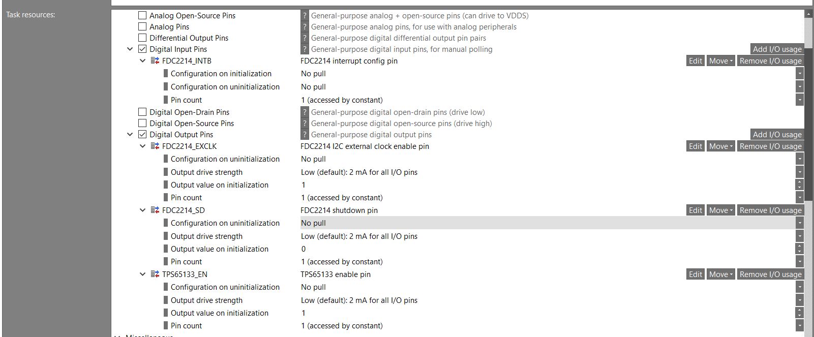
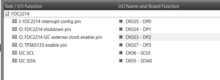
In the code below, I changed the settings of DP0/1/2/3 in const PIN_Config BoardGpioInitTable[] = {} to achieve the configuration in the above figure.
/*
 * Copyright (c) 2015-2016, Texas Instruments Incorporated
 * All rights reserved.
 *
 * Redistribution and use in source and binary forms, with or without
 * modification, are permitted provided that the following conditions
 * are met:
 *
 * *  Redistributions of source code must retain the above copyright
 *    notice, this list of conditions and the following disclaimer.
 *
 * *  Redistributions in binary form must reproduce the above copyright
 *    notice, this list of conditions and the following disclaimer in the
 *    documentation and/or other materials provided with the distribution.
 *
 * *  Neither the name of Texas Instruments Incorporated nor the names of
 *    its contributors may be used to endorse or promote products derived
 *    from this software without specific prior written permission.
 *
 * THIS SOFTWARE IS PROVIDED BY THE COPYRIGHT HOLDERS AND CONTRIBUTORS "AS IS"
 * AND ANY EXPRESS OR IMPLIED WARRANTIES, INCLUDING, BUT NOT LIMITED TO,
 * THE IMPLIED WARRANTIES OF MERCHANTABILITY AND FITNESS FOR A PARTICULAR
 * PURPOSE ARE DISCLAIMED. IN NO EVENT SHALL THE COPYRIGHT OWNER OR
 * CONTRIBUTORS BE LIABLE FOR ANY DIRECT, INDIRECT, INCIDENTAL, SPECIAL,
 * EXEMPLARY, OR CONSEQUENTIAL DAMAGES (INCLUDING, BUT NOT LIMITED TO,
 * PROCUREMENT OF SUBSTITUTE GOODS OR SERVICES; LOSS OF USE, DATA, OR PROFITS;
 * OR BUSINESS INTERRUPTION) HOWEVER CAUSED AND ON ANY THEORY OF LIABILITY,
 * WHETHER IN CONTRACT, STRICT LIABILITY, OR TORT (INCLUDING NEGLIGENCE OR
 * OTHERWISE) ARISING IN ANY WAY OUT OF THE USE OF THIS SOFTWARE,
 * EVEN IF ADVISED OF THE POSSIBILITY OF SUCH DAMAGE.
 */

/*
 *  ====================== CC2650STK.c =========================================
 *  This file is responsible for setting up the board specific items for the
 *  CC2650 SensorTag.
 */


/*
 *  ====================== Includes ============================================
 */
#include <xdc/std.h>
#include <xdc/runtime/System.h>

#include <ti/sysbios/family/arm/m3/Hwi.h>
#include <ti/drivers/PIN.h>
#include <ti/drivers/pin/PINCC26XX.h>
#include <ti/drivers/PWM.h>
#include <ti/drivers/pwm/PWMTimerCC26XX.h>
#include <ti/drivers/timer/GPTimerCC26XX.h>
#include <ti/drivers/Power.h>
#include <ti/drivers/power/PowerCC26XX.h>

#include <inc/hw_memmap.h>
#include <inc/hw_ints.h>
#include <driverlib/ioc.h>
#include <driverlib/udma.h>

#include <Board.h>

/*
 *  ========================= IO driver initialization =========================
 *  From main, PIN_init(BoardGpioInitTable) should be called to setup safe
 *  settings for this board.
 *  When a pin is allocated and then de-allocated, it will revert to the state
 *  configured in this table.
 */
/* Place into subsections to allow the TI linker to remove items properly */
#if defined(__TI_COMPILER_VERSION__)
#pragma DATA_SECTION(BoardGpioInitTable, ".const:BoardGpioInitTable")
#pragma DATA_SECTION(PINCC26XX_hwAttrs, ".const:PINCC26XX_hwAttrs")
#endif

const PIN_Config BoardGpioInitTable[] = {

    Board_STK_LED1   | PIN_GPIO_OUTPUT_EN | PIN_GPIO_LOW | PIN_PUSHPULL | PIN_DRVSTR_MAX,     /* LED initially off             */
    Board_STK_LED2   | PIN_GPIO_OUTPUT_EN | PIN_GPIO_LOW | PIN_PUSHPULL | PIN_DRVSTR_MAX,     /* LED initially off             */
    Board_KEY_LEFT   | PIN_INPUT_EN | PIN_PULLUP | PIN_IRQ_BOTHEDGES | PIN_HYSTERESIS,        /* Button is active low          */
    Board_KEY_RIGHT  | PIN_INPUT_EN | PIN_PULLUP | PIN_IRQ_BOTHEDGES | PIN_HYSTERESIS,        /* Button is active low          */
    Board_RELAY      | PIN_INPUT_EN | PIN_PULLDOWN | PIN_IRQ_BOTHEDGES | PIN_HYSTERESIS,      /* Relay is active high          */
    Board_MPU_INT    | PIN_INPUT_EN | PIN_PULLDOWN | PIN_IRQ_NEGEDGE | PIN_HYSTERESIS,        /* MPU_INT is active low         */
    Board_TMP_RDY    | PIN_INPUT_EN | PIN_PULLUP | PIN_HYSTERESIS,                            /* TMP_RDY is active high        */
    Board_BUZZER     | PIN_GPIO_OUTPUT_EN | PIN_GPIO_LOW | PIN_PUSHPULL | PIN_DRVSTR_MAX,     /* Buzzer initially off          */
    Board_MPU_POWER  | PIN_GPIO_OUTPUT_EN | PIN_GPIO_HIGH | PIN_PUSHPULL | PIN_DRVSTR_MAX,    /* MPU initially on              */
    Board_MIC_POWER  | PIN_GPIO_OUTPUT_EN | PIN_GPIO_LOW | PIN_PUSHPULL | PIN_DRVSTR_MIN,     /* MIC initially off             */
    Board_SPI_FLASH_CS | PIN_GPIO_OUTPUT_EN | PIN_GPIO_HIGH | PIN_PUSHPULL | PIN_DRVSTR_MIN,  /* External flash chip select    */
    Board_SPI_DEVPK_CS | PIN_GPIO_OUTPUT_EN | PIN_GPIO_LOW | PIN_PUSHPULL | PIN_DRVSTR_MIN,   /* DevPack chip select           */
    Board_AUDIO_DI | PIN_INPUT_EN | PIN_PULLDOWN,                                             /* Audio DI                      */
    Board_AUDIODO | PIN_GPIO_OUTPUT_EN | PIN_GPIO_HIGH | PIN_PUSHPULL | PIN_DRVSTR_MIN,       /* Audio data out                */
    Board_AUDIO_CLK | PIN_INPUT_EN | PIN_PULLDOWN,                                            /* DevPack */

    /* DP0-3 configuration for FDC2214 */
    Board_DP2 | PIN_GPIO_OUTPUT_EN | PIN_GPIO_HIGH | PIN_PUSHPULL | PIN_DRVSTR_MIN,           /* FDC2214 external clock enable */
    Board_DP1 | PIN_GPIO_OUTPUT_EN | PIN_GPIO_LOW | PIN_PUSHPULL | PIN_DRVSTR_MIN,            /* FDC2214 SD */
    Board_DP0 | PIN_INPUT_EN | PIN_NOPULL,                                                    /* FDC2214 INTB  */
    Board_DP3 | PIN_GPIO_OUTPUT_EN | PIN_GPIO_LOW | PIN_PUSHPULL | PIN_DRVSTR_MIN,            /* TPS65133 enable */
    /* The end of FDC2214 configuration */

    Board_UART_RX | PIN_INPUT_EN | PIN_PULLDOWN,                                              /* DevPack */
    Board_UART_TX | PIN_GPIO_OUTPUT_EN | PIN_GPIO_HIGH | PIN_PUSHPULL,                        /* DevPack */
    Board_DEVPK_ID | PIN_INPUT_EN | PIN_NOPULL,                                               /* Device pack ID - external PU  */
    Board_SPI0_MOSI | PIN_INPUT_EN | PIN_PULLDOWN,                                            /* SPI master out - slave in */
    Board_SPI0_MISO | PIN_INPUT_EN | PIN_PULLDOWN,                                            /* SPI master in - slave out */
    Board_SPI0_CLK | PIN_INPUT_EN | PIN_PULLDOWN,                                             /* SPI clock */

    PIN_TERMINATE
};

const PINCC26XX_HWAttrs PINCC26XX_hwAttrs = {
    .intPriority = ~0,
    .swiPriority = 0
};
/*============================================================================*/

/*
 *  ============================= Power begin ==================================
 */
/* Place into subsections to allow the TI linker to remove items properly */
#if defined(__TI_COMPILER_VERSION__)
#pragma DATA_SECTION(PowerCC26XX_config, ".const:PowerCC26XX_config")
#endif
const PowerCC26XX_Config PowerCC26XX_config = {
    .policyInitFxn      = NULL,
    .policyFxn          = &PowerCC26XX_standbyPolicy,
    .calibrateFxn       = &PowerCC26XX_calibrate,
    .enablePolicy       = TRUE,
    .calibrateRCOSC_LF  = TRUE,
    .calibrateRCOSC_HF  = TRUE,
};
/*
 *  ============================= Power end ===================================
 */

/*
 *  ============================= UART begin ===================================
 */
/* Place into subsections to allow the TI linker to remove items properly */
#if defined(__TI_COMPILER_VERSION__)
#pragma DATA_SECTION(UART_config, ".const:UART_config")
#pragma DATA_SECTION(uartCC26XXHWAttrs, ".const:uartCC26XXHWAttrs")
#endif

/* Include drivers */
#include <ti/drivers/UART.h>
#include <ti/drivers/uart/UARTCC26XX.h>

/* UART objects */
UARTCC26XX_Object uartCC26XXObjects[CC2650STK_UARTCOUNT];
unsigned char uartCC26XXRingBuffer[CC2650STK_UARTCOUNT][32];

/* UART hardware parameter structure, also used to assign UART pins */
const UARTCC26XX_HWAttrsV2 uartCC26XXHWAttrs[CC2650STK_UARTCOUNT] = {
    {
        .baseAddr       = UART0_BASE,
        .powerMngrId    = PowerCC26XX_PERIPH_UART0,
        .intNum         = INT_UART0_COMB,
        .intPriority    = ~0,
        .swiPriority    = 0,
        .txPin          = Board_UART_TX,
        .rxPin          = Board_UART_RX,
        .ctsPin         = PIN_UNASSIGNED,
        .rtsPin         = PIN_UNASSIGNED,
        .ringBufPtr     = uartCC26XXRingBuffer[0],
        .ringBufSize    = sizeof(uartCC26XXRingBuffer[0])
    }
};

/* UART configuration structure */
const UART_Config UART_config[] = {
    {
        .fxnTablePtr = &UARTCC26XX_fxnTable,
        .object      = &uartCC26XXObjects[0],
        .hwAttrs     = &uartCC26XXHWAttrs[0]
    },
    {NULL, NULL, NULL}
};
/*
 *  ============================= UART end =====================================
 */

/*
 *  ============================= UDMA begin ===================================
 */
/* Place into subsections to allow the TI linker to remove items properly */
#if defined(__TI_COMPILER_VERSION__)
#pragma DATA_SECTION(UDMACC26XX_config, ".const:UDMACC26XX_config")
#pragma DATA_SECTION(udmaHWAttrs, ".const:udmaHWAttrs")
#endif

/* Include drivers */
#include <ti/drivers/dma/UDMACC26XX.h>

/* UDMA objects */
UDMACC26XX_Object udmaObjects[CC2650STK_UDMACOUNT];

/* UDMA configuration structure */
const UDMACC26XX_HWAttrs udmaHWAttrs[CC2650STK_UDMACOUNT] = {
    {
        .baseAddr    = UDMA0_BASE,
        .powerMngrId = PowerCC26XX_PERIPH_UDMA,
        .intNum      = INT_DMA_ERR,
        .intPriority = ~0
    }
};

/* UDMA configuration structure */
const UDMACC26XX_Config UDMACC26XX_config[] = {
    {
         .object  = &udmaObjects[0],
         .hwAttrs = &udmaHWAttrs[0]
    },
    {NULL, NULL}
};
/*
 *  ============================= UDMA end =====================================
 */

/*
 *  ========================== SPI DMA begin ===================================
 */
/* Place into subsections to allow the TI linker to remove items properly */
#if defined(__TI_COMPILER_VERSION__)
#pragma DATA_SECTION(SPI_config, ".const:SPI_config")
#pragma DATA_SECTION(spiCC26XXDMAHWAttrs, ".const:spiCC26XXDMAHWAttrs")
#endif

/* Include drivers */
#include <ti/drivers/spi/SPICC26XXDMA.h>

/* SPI objects */
SPICC26XXDMA_Object spiCC26XXDMAObjects[CC2650STK_SPICOUNT];

/* SPI configuration structure, describing which pins are to be used */
const SPICC26XXDMA_HWAttrsV1 spiCC26XXDMAHWAttrs[CC2650STK_SPICOUNT] = {
    {
        .baseAddr           = SSI0_BASE,
        .intNum             = INT_SSI0_COMB,
        .intPriority        = ~0,
        .swiPriority        = 0,
        .powerMngrId        = PowerCC26XX_PERIPH_SSI0,
        .defaultTxBufValue  = 0,
        .rxChannelBitMask   = 1<<UDMA_CHAN_SSI0_RX,
        .txChannelBitMask   = 1<<UDMA_CHAN_SSI0_TX,
        .mosiPin            = Board_SPI0_MOSI,
        .misoPin            = Board_SPI0_MISO,
        .clkPin             = Board_SPI0_CLK,
        .csnPin             = Board_SPI0_CSN
    },
    {
        .baseAddr           = SSI1_BASE,
        .intNum             = INT_SSI1_COMB,
        .intPriority        = ~0,
        .swiPriority        = 0,
        .powerMngrId        = PowerCC26XX_PERIPH_SSI1,
        .defaultTxBufValue  = 0,
        .rxChannelBitMask   = 1<<UDMA_CHAN_SSI1_RX,
        .txChannelBitMask   = 1<<UDMA_CHAN_SSI1_TX,
        .mosiPin            = Board_SPI1_MOSI,
        .misoPin            = Board_SPI1_MISO,
        .clkPin             = Board_SPI1_CLK,
        .csnPin             = Board_SPI1_CSN
    }
};

/* SPI configuration structure */
const SPI_Config SPI_config[] = {
    {
         .fxnTablePtr = &SPICC26XXDMA_fxnTable,
         .object      = &spiCC26XXDMAObjects[0],
         .hwAttrs     = &spiCC26XXDMAHWAttrs[0]
    },
    {
         .fxnTablePtr = &SPICC26XXDMA_fxnTable,
         .object      = &spiCC26XXDMAObjects[1],
         .hwAttrs     = &spiCC26XXDMAHWAttrs[1]
    },
    {NULL, NULL, NULL}
};
/*
 *  ========================== SPI DMA end =====================================
*/


/*
 *  ============================= I2C Begin=====================================
*/
/* Place into subsections to allow the TI linker to remove items properly */
#if defined(__TI_COMPILER_VERSION__)
#pragma DATA_SECTION(I2C_config, ".const:I2C_config")
#pragma DATA_SECTION(i2cCC26xxHWAttrs, ".const:i2cCC26xxHWAttrs")
#endif

/* Include drivers */
#include <ti/drivers/i2c/I2CCC26XX.h>

/* I2C objects */
I2CCC26XX_Object i2cCC26xxObjects[CC2650STK_I2CCOUNT];

/* I2C configuration structure, describing which pins are to be used */
const I2CCC26XX_HWAttrsV1 i2cCC26xxHWAttrs[CC2650STK_I2CCOUNT] = {
    {
        .baseAddr = I2C0_BASE,
        .powerMngrId = PowerCC26XX_PERIPH_I2C0,
        .intNum = INT_I2C_IRQ,
        .intPriority = ~0,
        .swiPriority = 0,
        .sdaPin = Board_I2C0_SDA0,
        .sclPin = Board_I2C0_SCL0,
    }
};

const I2C_Config I2C_config[] = {
    {
        .fxnTablePtr = &I2CCC26XX_fxnTable,
        .object = &i2cCC26xxObjects[0],
        .hwAttrs = &i2cCC26xxHWAttrs[0]
    },
    {NULL, NULL, NULL}
};
/*
 *  ========================== I2C end =========================================
 */

/*
 *  ========================== Crypto begin ====================================
 *  NOTE: The Crypto implementation should be considered experimental
 *        and not validated!
 */
/* Place into subsections to allow the TI linker to remove items properly */
#if defined(__TI_COMPILER_VERSION__)
#pragma DATA_SECTION(CryptoCC26XX_config, ".const:CryptoCC26XX_config")
#pragma DATA_SECTION(cryptoCC26XXHWAttrs, ".const:cryptoCC26XXHWAttrs")
#endif

/* Include drivers */
#include <ti/drivers/crypto/CryptoCC26XX.h>

/* Crypto objects */
CryptoCC26XX_Object cryptoCC26XXObjects[CC2650STK_CRYPTOCOUNT];

/* Crypto configuration structure, describing which pins are to be used */
const CryptoCC26XX_HWAttrs cryptoCC26XXHWAttrs[CC2650STK_CRYPTOCOUNT] = {
    {
        .baseAddr       = CRYPTO_BASE,
        .powerMngrId    = PowerCC26XX_PERIPH_CRYPTO,
        .intNum         = INT_CRYPTO_RESULT_AVAIL_IRQ,
        .intPriority    = ~0,
    }
};

/* Crypto configuration structure */
const CryptoCC26XX_Config CryptoCC26XX_config[] = {
    {
         .object  = &cryptoCC26XXObjects[0],
         .hwAttrs = &cryptoCC26XXHWAttrs[0]
    },
    {NULL, NULL}
};
/*
 *  ========================== Crypto end ======================================
 */

/*
 *  ============================= PDM begin ====================================
 */
/* Place into subsections to allow the TI linker to remove items properly */
#if defined(__TI_COMPILER_VERSION__)
#pragma DATA_SECTION(PDMCC26XX_config, ".const:PDMCC26XX_config")
#pragma DATA_SECTION(pdmCC26XXHWAttrs, ".const:pdmCC26XXHWAttrs")
#pragma DATA_SECTION(pdmC26XXI2SHWAttrs, ".const:pdmC26XXI2SHWAttrs")
#pragma DATA_SECTION(PDMCC26XX_I2S_config, ".const:PDMCC26XX_I2S_config")
#endif

/* Include drivers */
#include <ti/drivers/pdm/PDMCC26XX.h>
#include <ti/drivers/pdm/PDMCC26XX_util.h>

/* PDM objects, one for PDM driver, one for PDM/I2S helper file */
PDMCC26XX_Object pdmCC26XXObjects[CC2650STK_PDMCOUNT];
PDMCC26XX_I2S_Object pdmCC26XXI2SObjects[CC2650STK_PDMCOUNT];

/* PDM driver hardware attributes */
const PDMCC26XX_HWAttrs pdmCC26XXHWAttrs[CC2650STK_PDMCOUNT] = {
    {
        .micPower = Board_MIC_POWER,
        .taskPriority = 2
    }
};

/* PDM configuration structure */
const PDMCC26XX_Config PDMCC26XX_config[] = {
    {
        .object = &pdmCC26XXObjects[0],
        .hwAttrs = &pdmCC26XXHWAttrs[0]
    }
};

/* PDM_I2S hardware attributes */
const PDMCC26XX_I2S_HWAttrs pdmC26XXI2SHWAttrs[CC2650STK_PDMCOUNT] = {
    {
        .baseAddr       = I2S0_BASE,
        .intNum         = INT_I2S_IRQ,
        .powerMngrId    = PowerCC26XX_PERIPH_I2S,
        .intPriority    = ~0,
        .mclkPin        = PIN_UNASSIGNED,
        .bclkPin        = Board_AUDIO_CLK,
        .wclkPin        = PIN_UNASSIGNED,
        .ad0Pin         = Board_AUDIO_DI,
    }
};

/* PDM_I2S configuration structure */
const PDMCC26XX_I2S_Config PDMCC26XX_I2S_config[] = {
    {
        .object  = &pdmCC26XXI2SObjects[0],
        .hwAttrs = &pdmC26XXI2SHWAttrs[0]
    },
    { NULL, NULL }
};

/*
 *  ============================= PDM end ======================================
 */

/*
 *  ========================= RF driver begin ==================================
 */
/* Place into subsections to allow the TI linker to remove items properly */
#if defined(__TI_COMPILER_VERSION__)
#pragma DATA_SECTION(RFCC26XX_hwAttrs, ".const:RFCC26XX_hwAttrs")
#endif

/* Include drivers */
#include <ti/drivers/rf/RF.h>

/* RF hwi and swi priority */
const RFCC26XX_HWAttrs RFCC26XX_hwAttrs = {
    .hwiCpe0Priority = ~0,
    .hwiHwPriority   = ~0,
    .swiCpe0Priority =  0,
    .swiHwPriority   =  0,
};

/*
 *  ========================== RF driver end ===================================
 */

/*
 *  ========================= Display begin ====================================
 */
/* Place into subsections to allow the TI linker to remove items properly */
#if defined(__TI_COMPILER_VERSION__)
#pragma DATA_SECTION(Display_config, ".const:Display_config")
#pragma DATA_SECTION(displaySharpHWattrs, ".const:displaySharpHWattrs")
#pragma DATA_SECTION(displayUartHWAttrs, ".const:displayUartHWAttrs")
#endif

#include <ti/mw/display/Display.h>
#include <ti/mw/display/DisplaySharp.h>
#include <ti/mw/display/DisplayUart.h>

/* Structures for UartPlain Blocking */
DisplayUart_Object        displayUartObject;

#ifndef BOARD_DISPLAY_UART_STRBUF_SIZE
#define BOARD_DISPLAY_UART_STRBUF_SIZE    128
#endif
static char uartStringBuf[BOARD_DISPLAY_UART_STRBUF_SIZE];

const DisplayUart_HWAttrs displayUartHWAttrs = {
    .uartIdx      = Board_UART,
    .baudRate     =     115200,
    .mutexTimeout = BIOS_WAIT_FOREVER,
    .strBuf = uartStringBuf,
    .strBufLen = BOARD_DISPLAY_UART_STRBUF_SIZE,
};

/* Structures for SHARP */
DisplaySharp_Object displaySharpObject;

#ifndef BOARD_DISPLAY_SHARP_SIZE
#define BOARD_DISPLAY_SHARP_SIZE    96 // 96->96x96 is the most common board, alternative is 128->128x128.
#endif
static uint8_t sharpDisplayBuf[BOARD_DISPLAY_SHARP_SIZE * BOARD_DISPLAY_SHARP_SIZE / 8];

const DisplaySharp_HWAttrs displaySharpHWattrs = {
    .spiIndex    = Board_SPI0,
    .csPin       = Board_LCD_CS,
    .extcominPin = Board_LCD_EXTCOMIN,
    .powerPin    = Board_LCD_POWER,
    .enablePin   = Board_LCD_ENABLE,
    .pixelWidth  = BOARD_DISPLAY_SHARP_SIZE,
    .pixelHeight = BOARD_DISPLAY_SHARP_SIZE,
    .displayBuf  = sharpDisplayBuf,
};

/* As the pins for UART and Watch Devpack conflict, prefer UART by default */
#if !defined(BOARD_DISPLAY_EXCLUDE_UART) && !defined(BOARD_DISPLAY_EXCLUDE_LCD)
#  define BOARD_DISPLAY_EXCLUDE_LCD
#endif

/* Array of displays */
const Display_Config Display_config[] = {
#if !defined(BOARD_DISPLAY_EXCLUDE_UART)
    {
        .fxnTablePtr = &DisplayUart_fxnTable,
        .object      = &displayUartObject,
        .hwAttrs     = &displayUartHWAttrs,
    },
#endif
#if !defined(BOARD_DISPLAY_EXCLUDE_LCD)
    {
        .fxnTablePtr = &DisplaySharp_fxnTable,
        .object      = &displaySharpObject,
        .hwAttrs     = &displaySharpHWattrs
    },
#endif
    { NULL, NULL, NULL } // Terminator
};

/*
 *  ========================= Display end ======================================
 */

/*
 *  ============================ GPTimer begin =================================
 *  Remove unused entries to reduce flash usage both in Board.c and Board.h
 */
/* Place into subsections to allow the TI linker to remove items properly */
#if defined(__TI_COMPILER_VERSION__)
#pragma DATA_SECTION(GPTimerCC26XX_config, ".const:GPTimerCC26XX_config")
#pragma DATA_SECTION(gptimerCC26xxHWAttrs, ".const:gptimerCC26xxHWAttrs")
#endif

/* GPTimer hardware attributes, one per timer part (Timer 0A, 0B, 1A, 1B..) */
const GPTimerCC26XX_HWAttrs gptimerCC26xxHWAttrs[CC2650STK_GPTIMERPARTSCOUNT] = {
    { .baseAddr = GPT0_BASE, .intNum = INT_GPT0A, .intPriority = (~0), .powerMngrId = PowerCC26XX_PERIPH_GPT0, .pinMux = GPT_PIN_0A, },
    { .baseAddr = GPT0_BASE, .intNum = INT_GPT0B, .intPriority = (~0), .powerMngrId = PowerCC26XX_PERIPH_GPT0, .pinMux = GPT_PIN_0B, },
    { .baseAddr = GPT1_BASE, .intNum = INT_GPT1A, .intPriority = (~0), .powerMngrId = PowerCC26XX_PERIPH_GPT1, .pinMux = GPT_PIN_1A, },
    { .baseAddr = GPT1_BASE, .intNum = INT_GPT1B, .intPriority = (~0), .powerMngrId = PowerCC26XX_PERIPH_GPT1, .pinMux = GPT_PIN_1B, },
    { .baseAddr = GPT2_BASE, .intNum = INT_GPT2A, .intPriority = (~0), .powerMngrId = PowerCC26XX_PERIPH_GPT2, .pinMux = GPT_PIN_2A, },
    { .baseAddr = GPT2_BASE, .intNum = INT_GPT2B, .intPriority = (~0), .powerMngrId = PowerCC26XX_PERIPH_GPT2, .pinMux = GPT_PIN_2B, },
    { .baseAddr = GPT3_BASE, .intNum = INT_GPT3A, .intPriority = (~0), .powerMngrId = PowerCC26XX_PERIPH_GPT3, .pinMux = GPT_PIN_3A, },
    { .baseAddr = GPT3_BASE, .intNum = INT_GPT3B, .intPriority = (~0), .powerMngrId = PowerCC26XX_PERIPH_GPT3, .pinMux = GPT_PIN_3B, },
};

/*  GPTimer objects, one per full-width timer (A+B) (Timer 0, Timer 1..) */
GPTimerCC26XX_Object gptimerCC26XXObjects[CC2650STK_GPTIMERCOUNT];

/* GPTimer configuration (used as GPTimer_Handle by driver and application) */
const GPTimerCC26XX_Config GPTimerCC26XX_config[CC2650STK_GPTIMERPARTSCOUNT] = {
    { &gptimerCC26XXObjects[0], &gptimerCC26xxHWAttrs[0], GPT_A },
    { &gptimerCC26XXObjects[0], &gptimerCC26xxHWAttrs[1], GPT_B },
    { &gptimerCC26XXObjects[1], &gptimerCC26xxHWAttrs[2], GPT_A },
    { &gptimerCC26XXObjects[1], &gptimerCC26xxHWAttrs[3], GPT_B },
    { &gptimerCC26XXObjects[2], &gptimerCC26xxHWAttrs[4], GPT_A },
    { &gptimerCC26XXObjects[2], &gptimerCC26xxHWAttrs[5], GPT_B },
    { &gptimerCC26XXObjects[3], &gptimerCC26xxHWAttrs[6], GPT_A },
    { &gptimerCC26XXObjects[3], &gptimerCC26xxHWAttrs[7], GPT_B },
};

/*
 *  ============================ GPTimer end ===================================
 */


/*
 *  ============================= PWM begin ====================================
 *  Remove unused entries to reduce flash usage both in Board.c and Board.h
 */
/* Place into subsections to allow the TI linker to remove items properly */
#if defined(__TI_COMPILER_VERSION__)
#pragma DATA_SECTION(PWM_config, ".const:PWM_config")
#pragma DATA_SECTION(pwmtimerCC26xxHWAttrs, ".const:pwmtimerCC26xxHWAttrs")
#endif

/* PWM configuration, one per PWM output.   */
PWMTimerCC26XX_HwAttrs pwmtimerCC26xxHWAttrs[CC2650STK_PWMCOUNT] = {
    { .pwmPin = Board_PWMPIN0, .gpTimerUnit = Board_GPTIMER0A },
    { .pwmPin = Board_PWMPIN1, .gpTimerUnit = Board_GPTIMER0B },
    { .pwmPin = Board_PWMPIN2, .gpTimerUnit = Board_GPTIMER1A },
    { .pwmPin = Board_PWMPIN3, .gpTimerUnit = Board_GPTIMER1B },
    { .pwmPin = Board_PWMPIN4, .gpTimerUnit = Board_GPTIMER2A },
    { .pwmPin = Board_PWMPIN5, .gpTimerUnit = Board_GPTIMER2B },
    { .pwmPin = Board_PWMPIN6, .gpTimerUnit = Board_GPTIMER3A },
    { .pwmPin = Board_PWMPIN7, .gpTimerUnit = Board_GPTIMER3B },
};

/* PWM object, one per PWM output */
PWMTimerCC26XX_Object pwmtimerCC26xxObjects[CC2650STK_PWMCOUNT];

extern const PWM_FxnTable PWMTimerCC26XX_fxnTable;

/* PWM configuration (used as PWM_Handle by driver and application) */
const PWM_Config PWM_config[CC2650STK_PWMCOUNT + 1] = {
    { &PWMTimerCC26XX_fxnTable, &pwmtimerCC26xxObjects[0], &pwmtimerCC26xxHWAttrs[0] },
    { &PWMTimerCC26XX_fxnTable, &pwmtimerCC26xxObjects[1], &pwmtimerCC26xxHWAttrs[1] },
    { &PWMTimerCC26XX_fxnTable, &pwmtimerCC26xxObjects[2], &pwmtimerCC26xxHWAttrs[2] },
    { &PWMTimerCC26XX_fxnTable, &pwmtimerCC26xxObjects[3], &pwmtimerCC26xxHWAttrs[3] },
    { &PWMTimerCC26XX_fxnTable, &pwmtimerCC26xxObjects[4], &pwmtimerCC26xxHWAttrs[4] },
    { &PWMTimerCC26XX_fxnTable, &pwmtimerCC26xxObjects[5], &pwmtimerCC26xxHWAttrs[5] },
    { &PWMTimerCC26XX_fxnTable, &pwmtimerCC26xxObjects[6], &pwmtimerCC26xxHWAttrs[6] },
    { &PWMTimerCC26XX_fxnTable, &pwmtimerCC26xxObjects[7], &pwmtimerCC26xxHWAttrs[7] },
    { NULL,                NULL,                 NULL                 }
};


/*
 *  ============================= PWM end ======================================
 */

/*
 *  =============================== Watchdog ===============================
 */
/* Place into subsections to allow the TI linker to remove items properly */
#if defined(__TI_COMPILER_VERSION__)
#pragma DATA_SECTION(Watchdog_config, ".const:Watchdog_config")
#pragma DATA_SECTION(watchdogCC26XXHWAttrs, ".const:watchdogCC26XXHWAttrs")
#endif

#include <ti/drivers/Watchdog.h>
#include <ti/drivers/watchdog/WatchdogCC26XX.h>

WatchdogCC26XX_Object watchdogCC26XXObjects[CC2650STK_WATCHDOGCOUNT];

const WatchdogCC26XX_HWAttrs watchdogCC26XXHWAttrs[CC2650STK_WATCHDOGCOUNT] = {
    {
        .baseAddr = WDT_BASE,
        .intNum = INT_WDT_IRQ,
        .reloadValue = 1000 /* Reload value in milliseconds */
    },
};

const Watchdog_Config Watchdog_config[] = {
    {
        .fxnTablePtr = &WatchdogCC26XX_fxnTable,
        .object = &watchdogCC26XXObjects[0],
        .hwAttrs = &watchdogCC26XXHWAttrs[0]
    },
    {NULL, NULL, NULL},
};

/*
 *  ======== CC26XX_LAUNCHXL_initWatchdog ========
 */
void CC26XX_LAUNCHXL_initWatchdog(void)
{
    Watchdog_init();
}
Regards,
Will

