This thread has been locked.

If you have a related question, please click the "Ask a related question" button in the top right corner. The newly created question will be automatically linked to this question.

CC2651R3: unsure of UART pins

Part Number: CC2651R3

Hi Team, 

Good day. I am posting this inquiry on behalf of the customer.

I'm designing a board using the CC2651R3SIPA module. I'm trying to use the UART pins for bootloading. however, the reference design for the dev kit and the technical reference manual have conflicting information regarding the CC2651R UART pins.

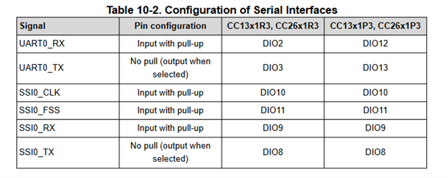
In the technical reference manual, we have the following table where the relevant pins are labeled DIO2 and DIO3

However, in the reference design, they use different pins for the same chip

Some clarification would be much appreciated.

also, what is meant by input with pull-up? are they referring to an internal pull-up resistor or an external one I have to add to my schematic?

Thank you for your support.

Please help to advise. Thank you for extending your support.

Kind regards,

Marvin

  • Hi Marvin,

    The peripherals on the CC2651R3SIPA have highly flexible multiplexing options and can be brought out to any of the DIO pins. Table 10-2 refers to the pin configuration when using the ROM based bootloader. On the LaunchPad we're not relying on the ROM bootloader functionality and so have used other pins, in this case DIO12 and DIO13 for the UART. I don't know the historical reason why that was done. In our other LaunchPad designs it's typical to use the bootloader UART pins. If you do want to use the ROM based bootloader in your design then you would need to make sure to make the appropriate pins available.

    In the table "Input with Pull-up" refers to the pin configuration. The pin is configured as an input and the internal pull-up is enabled. For more information on the pin muxing capability of the device see Chapter 13 from the Technical Reference Manual.

    -Jake