This thread has been locked.

If you have a related question, please click the "Ask a related question" button in the top right corner. The newly created question will be automatically linked to this question.

CC2650 ADC Reading incorrect values on SmartRF06 Evaluation board using sensor controller studio generated code

Other Parts Discussed in Thread: CC2650, CC2540

Using: SmartRF06 Eval board with CC2650EM board, Using Sensor Controller Studio  1.0.0.34897 (QFN48 7x7 RGZ) TI-RTOS Selected.

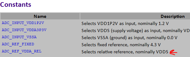
In regards to the Sensor Controller Studio. It is not clear from the documentation what level ADC_REF_VDDA_REL is. I connected a 1 volt bench power supply to to an ADC input and the ADC is measuring 1.305V.  

The following code is being used in the Sensor Controller Studio to read the values:

fwDelayUs(10000, FW_DELAY_RANGE_10_MS);

S16 adcValue;

adcEnableSync(ADC_REF_VDDA_REL, ADC_SAMPLE_TIME_10P6_US, ADC_TRIGGER_MANUAL);

adcGenManualTrigger();

adcReadFifo(adcValue);

state.adcValue = adcValue;

adcDisable();

output.measval = adcValue;

fwGenAlertInterrupt();

fwScheduleTask(1);

I confirmed that it is reading the correct ADC channel by connecting it to ground and measuring 0.002v.

There is no visibility in the Sensor Controller Studio documentation regarding changing ADC setup registers.  Is there a way to manually calibrate or configure the ADC within the SCS to yield accurate measurements,


  • Hi Robert,

    Reference material on the constants can be found by navigating to Sensor Controller Studio -> Help -> Sensor Controller Studio Help

    Within this file you can click ADC under Peripherals and it will show you the constant values, functions, etc.

    See below:

    From this chart you can observe the value of "ADC_REF_VDDA_REL" among others. Have you tried using the fixed reference instead?

    As for why the input is reading 1.35V when given 1.0V, I'm not sure about this; Eirik, could you chime in here?

    Best wishes,

    Lina

  • How to you calculate the voltage value?

    Have you tried to use ADC_REF_FIXED instead?
    By using the ADC_REF_VDDA_REL the reference will be dependent upon what the VDDS is which is 3.3V when powering from USB on the SmartRF06EB.
  • Eirik,

    Thanks for responding so quickly.  We tried both "Fixed" and "VDDA Rel", both yielded incorrect results.

    In our experiments, using VDDA Rel, when we connected 1.0V to the AUXIO pin, the raw value reported by the ADC was 1350 (base 10).  I assumed that the value was the measured voltage (in millivolt accuracy), and that the ADC was normalizing the value according to the selected reference voltage.

    Previously, when the thermistor reported 1.22V the ADC measured roughly 1.6V with VDDA Rel and 1.15V with Fixed.   With fixed, the measurement was always 70 mV off.   When I connected ground to the AUXIO pin, the ADC measured 0.002V on Fixed and VDDA Rel.

    Regards,

    Rob

  • I did some measurements with a lab bench power supply, and I measured the following data using ADC_REF_FIXED as a reference:

    Source V ADC Measured V delta delta/v
    0 0.002 0.002  
    0.1 0.094 -0.006 -0.06
    0.2 0.189 -0.011 -0.055
    0.3 0.283 -0.017 -0.05667
    0.4 0.378 -0.022 -0.055
    0.5 0.471 -0.029 -0.058
    0.6 0.565 -0.035 -0.05833
    0.7 0.66 -0.04 -0.05714
    0.8 0.752 -0.048 -0.06
    0.9 0.849 -0.051 -0.05667
    1 0.942 -0.058 -0.058
    1.1 1.034 -0.066 -0.06
    1.2 1.128 -0.072 -0.06
    1.3 1.223 -0.077 -0.05923
    1.4 1.317 -0.083 -0.05929

    The ADC measured data was universally off by -6%,

  • Hi Robert,

    Thanks for the data. While we work this on our end, could you answer the following:

    Have you tried using a different power supply to see if that affects your results? Or alternatively, could you verify the voltages you are feeding to the ADC on an accurate oscilloscope?

    Thanks,

    Lina

  • Lina, I verified the bench power supply with a couple of DMM's and they both report that the bench supply is accurate +/- 0.1mV . This difference is far less than the observed data form the ADC.
  • Hi Lina,
    Rob and I are working on this together. The Sensor Control Studio SW calculates a voltage based on the voltage at the ADC input pin. We have used 2 different ADC reference voltages (ADC_REF_FIXED and ADC_REF_VDDA_REL) which produce 2 different voltage readings . We do not have any visibility into the calculation which converts the ADC hex value into a voltage. Where can we find the formula which converts the raw ADC hex value into a voltage output? The CC2650 data sheet indicates that Vref=1.44V for the fixed reference option and Vref =VDDS/2.82= 1.17V for ADC_REF_VDDA_REL option. Does the SW automatically scale the ADC voltage calculation when Vref is changed? There was some mention in the documentation regarding calibration and offset values. Do we need to calibrate the ADC? If so, how would this be accomplished?
    Thank you,
    Doreen
  • Hello Doreen and Robert,

    The values you are reading are raw ADV values and does not correspond to mV or any other useful units. What I recommend is that you map the input voltages to raw values (as you have started to do) and then make implement this conversion with the application processor.

    If you adjust the input from 0V up to VDDS (Note: Do not insert any voltages higher than VDDs. When scaling is enabled (default), the internal fixed reference will seem to be 4.3 V, but the real internal value is 1.47 V. If you disable the scaling on the ADC input, the maximum voltage that can be applied is 1.49 V. This is all described in the 17.4.9 ADC subsection in the TRM and the CC2640 DS.

  • Eirik,

    While we calculated that the numbers reported by the ADC are off by 6% with regards to the input voltage, we are not comfortable just applying this factor without getting an understanding of why the 6% is needed. How do we know if the discrepancy is not related to a manufacturing issue on the development board or the CC2650EM module.  We could measure another system and need another scaling factor.

    Essentially, all the replies from TI so far on this have not explained why the ADC is reporting the numbers that it has.   The numbers reported by the ADC based on scaling being enabled or disabled are not what is expected given the VDDS voltage supplied to the system.

    We need to have a conference call next week with some TI engineers who can discuss this issue with us.  Clearly your documentation is not providing the information we need to resolve this issue.

  • Hello Robert,

    Have a look at the following thread which I believe dealt with a similar problem in regards to the CC2540.

    In any case, you will always need to apply some kind of factor to just about any ADC reading you get for an accurate reading.  That is because you want your ADC reading to match the readings from whatever measurement device you are using. The precision should always remains the same.

    Hope that helps.

    Thanks,

  • Hello Robert,

    Sorry for the delayed response on this specific post. I had to confer with R&D and Test to get some more info. I did a measurement myself with fixed reference (4.3 V) and got slightly better results (see table below). It should be possible to adjust gain and offset error based on values given in FCFG. I will investigate this and contact you with details through the Centralized Applications Team.

    But first can I ask you about the measurement setup?

    • Have you measured the input voltage on the actual pin to verify that you calculating based on correct input voltage?
    • I connected a supply directly in to the pin with no external components in my setup, did you do the same?
    Source Voltage (V) Raw ADC Value (REL) Converted Direct delta/v Raw ADC(FIXED) Converted Direct delta/v
    0 (0.0042) 11 0.008864469 NA (supply > 0)  11 0.011550672 NA (supply > 0)
    0.1 126 0.101538462 -0.015384615 97 0.101855922 0.018559219
    0.2 248 0.19985348 0.000732601 195 0.204761905 0.023809524
    0.3 360 0.29010989 0.032967033 288 0.302417582 0.008058608
    0.4 493 0.397289377 0.006776557 384 0.403223443 0.008058608
    0.5 613 0.493992674 0.012014652 480 0.504029304 0.008058608
    0.6 735 0.592307692 0.012820513 573 0.601684982 0.002808303
    0.7 855 0.689010989 0.015698587 669 0.702490842 0.003558346
    0.8 978 0.788131868 0.014835165 763 0.801196581 0.001495726
    0.9 1098 0.884835165 0.016849817 860 0.903052503 0.00339167
    1 1217 0.980732601 0.019267399 962 1.01015873 0.01015873
    1.1 1341 1.080659341 0.017582418 1047 1.099413919 -0.0005328
    1.2 1462 1.178168498 0.018192918 1143 1.20021978 0.00018315
    1.3 1583 1.275677656 0.018709496 1237 1.298925519 -0.00082652
    1.4 1706 1.374798535 0.018001047 1333 1.39973138 -0.00019187
    1.5 1827 1.472307692 0.018461538 1428 1.499487179 -0.00034188
    1.6 1947 1.569010989 0.019368132 1524 1.60029304 0.00018315
    1.7 2066 1.664908425 0.020642103 1618 1.698998779 -0.00058895
    1.8 2192 1.766446886 0.018640619 1713 1.798754579 -0.0006919
    1.9 2314 1.864761905 0.018546366 1808 1.898510379 -0.00078401
    2 2434 1.961465201 0.019267399 1902 1.997216117 -0.00139194
    2.5 3041 2.450622711 0.019750916 2375 2.493894994 -0.002442
    3 3648 2.93978022 0.02007326 2851 2.993724054 -0.00209198
    3.3 4011 3.232307692 0.020512821 3137 3.294041514 -0.0018056
  • Also it would be helpful if you can provide details on your software setup.
    It seems you are using TI RTOS, which version? The one included with the BLE stack?
  • So the inaccuracy that we are seeing goes from one generation of your devices to the next without being resolved?

    As we said before we were testing the ADC with a stable Lab Power Supply.  There is no variability.  we pumped in 1V and we did not get  anywhere close to 1V as the measurement, no matter the reference voltage selected.

    We have spent enough time trying to find an answer to this problem.  Unfortunately we will not be able to use the ADC on your part and we are switching to an external I2C based part to do the measurements.

    If applying a fudge factor is your final solution, your drivers should be doing this adjustment, and TI should be taking responsibility for this fabrication problem.  At least this way, should you fix the hardware problem in a later lot of parts, you can also adjust the fudge factor.    We as consumers should not be bearing the brunt of this.

    I've heard that someone at TI is working on such a driver change, but unfortunately the lead time of these changes does not fit in the timeframe needed for our project.

  • Hello Robert,

    In my experience, this is not a problem. Unless you can provide the exact setup you are using, including the size of the ground plain, routing etc., the calibration certificate of the power supply....

    As a test though, show us the results you get from the i2c ADC. From the result included, looking specifically at the RAW ADC values (which are not voltages) to the actual voltage (Converted direct), I would definitely like to see how an i2c ADC compares.

    Also, if you are using something like the SensorTag for these measurements, you have to take into consideration the lead lengths, routing etc., that will affect your readings.

    I have used the CC2540 for industrial thermocouple temperature measurements. Calibration was made against an NIST certified calibrator. The results were accurate across the entire voltage range, so I'm not sure if the problem you are running into is more related to your experience with higher performance MCUs with better ADCs or the fact that these MCUs ADCs require a greater adjustment than you are use to.

    Thanks,

    Thanks,
  • My first contribution to this forum:

    To solve my issues reading incorrect values from the ADC I needed a delay between AUXADCEnableSync() and AUXADCGenManualTrigger().

    Adding this delay the ADC works very well.


    Kind Regards,

    Simone Frau
  • Great contribution!
    Could you give some indication on the improvements you observed?
  • Yes of course:

    With the delay, I fixed it to 1 millisecond, I observe results really similar to your results described in the message of Apr 22, 2015 2:01 PM.

    If I remove the delay between AUXADCEnableSync() and AUXADCGenManualTrigger(), I have a fixed delta of 6% really similar to the results described by Robert Lieb in the message of Apr 17, 2015 9:39 PM.

    This result is totally independent from the configuration, with ADC_REF_FIXED or ADC_REF_VDDA_REL for reference voltage and with or without scaling.

    Kind Regards,

    Simone Frau