This thread has been locked.

If you have a related question, please click the "Ask a related question" button in the top right corner. The newly created question will be automatically linked to this question.

CC2652R: measuring the own current consumption with INA216 by using the sensor controller

Part Number: CC2652R
Other Parts Discussed in Thread: INA216, ENERGYTRACE

Hello,

I'am working with the CC2652R1 device. I read a lot of the sensor controller and how it works, but i can't achieve measuring the current of the CC2652R1 by using the INA216 and the SC. According the datasheet the SC should use some µA for measuring and processing, but i always measure the running SC and sleeping main CPU.

I'm using the RTC-based scheduling process for measuring n-samples (samples and clock are controlled by the M4, because i have to measure different currents at different execution events). I also tried the timer based measurement, but by using the timer, the SC does not go into the standby mode.

The figure below shows two red arrows, the first is the measured current, the second is the preferred position of the measurement.

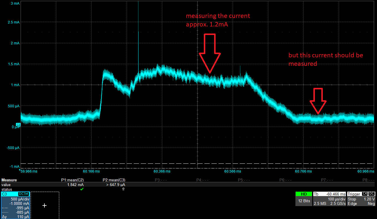
How can i measure the desired current? 

Thank you for your help!

  • Not quite following: You want to measure the current used using the SC (I assume that you use the ADC) when the SC is not on (which would be the case for the rightmost arrow)?

  • I'd like to measure the current consumption of the SoC with the SC (using the ADC). The desired measurement should be taken at the rightmost arrow (in this case the SC is in standby and only the M4 is running consuming approx. 200uA).

    Maybe there is a solution to trigger the measurement and go to standby?

    For instance a measure cycle: standby -> measure the current -> wake up and process -> got to standby -> repeat until the sample number is reached.

    The measurement should consume as less power as possible.

  • If you want to do a measurement with the ADC, the ADC have to be on, which it is at the leftmost arrow. Meaning that the SC has to be on when you do the measurement. 

  • This means there is no chance to measure the current consumption of the M4, because the SC + ADC needs approx. 1mA.

    How stable is the current consumption of the SC + ADC over the whole temperature range of the SoC? 

  • Could you give some background on why you want to use the chip to measure it's own current consumption?

    I have to check the temperature dependency of the ADC + SC

  • I'm developing a small form factor sensor for measurement tasks with a low power consumption as possible. Therefore i have to work together with a group of developers which don't have always access to an oscilloscope. The idea was to implement a current measurement to monitor the power consumption of each task (some with DSP functions) to find some improvements. Also some routines would need the current information.

  • If I understand you correctly you only need this for debugging. Wouldn't it be possible to have one DUT (for development of code) and then a second board for measuring the current? Then you can also use EnergyTrace on a Launchpad to get a fairly good overview over the power consumption. 

  • Kind of, an additional idea was that the SC should have measured the current of the M4 during the productive operation for some decisions.

    Hence we have to develop the code and check it with an oscilloscope or a Launchpad.  

    Thank you for your input and help. I'm awaiting the information of the temperature dependency of the ADC + SC.

  • It looks like the current consumption for the ADC is fairly temperature dependent, it looks like the current varies ~-30%/ +25 % compared to room temp. (low/ high temp)