


Other Parts Discussed in Thread: CC2541,
Introduction
In the BLEv1.2 release, support for Production Test Mode (PTM) has been added, allowing a BLE application in a "single-chip" configuration to temporarily expose the HCI over the UART interface when triggered externally to do so (e.g. hold a GPIO pin low during power up). This allows the device to be connected to a Bluetooth Tester in order to run Direct Test Mode (DTM) commands on a production line using the final release firmware, while leaving the UART GPIO pins available for the application to use at all other times.
Direct Test Mode (DTM)
There is a standard method for testing in BLE using the Direct Test Mode (DTM) HCI commands. A number of companies, including Anritsu (MT8852B) and Rhode and Schwarz make BLE Testers that make use of this mode. It is very useful to use these testers during development or in production line in order to verify the RF performance of BLE system. Complementary to these testers, it is possible to create your own PC application that sends these HCI commands over the serial link. DTM is very well described in the Bluetooth Core Specification Volume 6 Part F.
Production Test Mode (PTM)
One problem with DTM is that it relies on a certain stack configuration (network processor with HCI exposed over UART) in order to work with the testers, though many end-applications don’t use this configuration. This would require the customer, during production, to flash the CC254x with the network processor image before testing, and then re-flash with the final product image. To get around this, we have implemented the new feature in the v1.2 stack called Production Test Mode (PTM), which allows for a single software application to support production test mode without exposing the HCI to the UART pins under normal operation. PTM is set up to use HAL USART 0 UART, although those same pins can be used for the application UART interface. They just need to make sure that the other device that is connected to the UART interface does not run at the same time that DTM is being used. If the device powers up and goes into PTM mode (by a GPIO being held high or low), the UART is then used for DTM commands. If the device powers up normally and does not go into PTM mode, then the UART can be initialized by the application and used to communicate with the other device.
How to use Production Test Mode (PTM) on the CC254x
A PC is connected to one CC2540USB dongle running the HostTestRelease project (included with our SDK). The PC also has a UART connection with the Device Under Test (DUT). When the DUT is powered up, it must have one GPIO held the opposite of what it normally would be held. For example, if the GPIO normally has a resistor tied to ground on the PCB, you would need to make sure that before powering up for test that the pin is connected high to VDD. In the application source code initialization function, be sure that the following line of code is included:
#include “hci.h” if( GPIO == VDD ) // change the if statement to match the HW setup on the PCB { HCI_EXT_EnablePTM(); } With this code in the application and with the GPIO held high, the device will power up and the HCI_EXT_EnablePTM function will get called, which exposes the UART pins to enable test commands. As far as the USB dongle goes, you will need to have the driver loaded. The driver is included with our stack at C:\Texas Instruments\BLE-CC254x-1.2\Accessories\Drivers. This driver will create a Windows COM port for communication with the dongle. You will also have another Windows COM port for UART communication with the DUT. For communication with these devices, you will want to use the following port settings:
- Baud Rate = 115200 (or 57600)
- Flow Control = Hardware (CTS/RTS)
- Parity = None
- Stop Bits = 1
- Data Bits = 8
With both the dongle and DUT connected to PC COM ports, you will want to set the DUT in Tx test mode, and the dongle in Rx test mode over the COM ports (details on these commands below). You want to make sure that you send the commands to the two devices at the same time. The two devices will respond with an acknowledgement on the COM port and go into test modes. The device in Tx test mode will send one packet every 625 us. The device in Rx test mode will simply listen. After a period of time, you should send the test end command to both devices (again at the same time). Again the devices will both send acknowledgements back to the PC, though the dongle will include the total number of packets that were received while it was in Rx test mode. Based on the amount of time from start to finish, you will know how many packets were sent. After ending the Rx test you can see the number of packets received. With this you can calculate the PER. To test Rx on the DUT, you can put the dongle in Tx mode and put the DUT in Rx mode, repeating the same process but with roles reversed.
Test Commands
Command to start TX Test: HCI_LE_Transmitter_Test
Send this hex command to start Tx test: 01 1E 20 03 xx yy zz
xx = the channel you want to transmit on, any value from 0x00 to 0x27 (BLE channels go from 0 to 39)
yy = length of payload bytes in each test packet, which can be any value from 0x00 to 0x25
zz = code for the type of data in the packet payload. The following values can be used
0x00 Pseudo-Random bit sequence 9
0x01 Pattern of alternating bits ‘11110000’
0x02 Pattern of alternating bits ‘10101010’
0x03 Pseudo-Random bit sequence 15
0x04 Pattern of All ‘1’ bits
0x05 Pattern of All ‘0’ bits
0x06 Pattern of alternating bits ‘00001111’
0x07 Pattern of alternating bits ‘0101’
After sending the HCI_LE_Transmitter_Test command to the device, the following response will be returned, indicating that the command was received and the Tx test has begun: 04 0E 04 01 1E 20 00
Command to start Rx test: HCI_LE_Receiver_Test
Send this hex command to start Rx test: 01 1D 20 01 xx
xx = the channel you want to receive on, which can be any value from 0x00 to 0x27 (BLE channels go from 0 to 39)
After sending the HCI_LE_Receiver_Test command to the device, the following response will be returned, indicating that the command was received and the Rx test has begun: 04 0E 04 01 1D 20 00
Command to end either the Tx or Rx test: HCI_LE_Test_End
Send this hex command to end Rx or Tx test: 01 1f 20 00
After sending the HCI_LE_Test_End command to the device, the following response will be returned, indicating that the command was received and the test has ended: 04 0e 06 01 1f 20 00 xx xx
xx xx = 00 00 if Tx test was performed
xx xx = Total number of received packets if Rx test was performed.
How to Use PTM from an Application Point of View
This section presents how to enable PTM in the SimpleBLEPeripheral project, although the code can be used in any wanted project. This section shows how the application checks whether an MT8852B tester is connected during startup. It works by checking whether GPIO P0.4 is held low, and if it is then the application will enable PTM. Anritsu has implemented software in the MT8852B that will hold that line low to signal to the CC254x (Pin P0.4 is exposed on the DB-9 header connecting to the MT8852B). The other pins are the normal pins used for the HCI interface when using a network processor build. Essentially, all PTM does is allows you to expose the physical UART HCI interface in a single-chip build, only when triggered by some action during initialization. In the case of the sample code, the action is pin P0.4 being held down by the MT8852B. On the production line when the MT8852B is connected, the device will initialize into PTM. Under all other circumstances (such as when the end-user powers up the device as a final product), the GPIO will not be held low, so the device will initialize as normal. The HCI interface is not exposed to the physical UART interface, and those GPIO pins can be used by the application for anything. This allows one single software build to be used for both production testing as well as the final application.
Add the following preprocessors to your project options:
HAL_UART
HAL_DMA=TRUE
It is also important that you include the correct Transport Layer library so that PTM commands are routed correctly.
* In IAR, under the LIB folder
-
- Either remove or exclude from build the CC254x_BLE_HCI_TL_None.lib
- And add the PTM library file found at Projects\ble\Libraries\Common\bin\CC254x_BLE_HCI_TL_PTM.lib.
- If the file already in use was xxx_Full.lib, then you don't need to change anything.
Add following to constant declaration to your application (Ex. simpleBLEPeripheral.c)
#include "hci.h"
#define PTM                   4 //Pin to use to check if Tester is connected
#define RDY                   5
#define PDUP0                 5
#define P0ICON                0
#define TESTER_CONNECTED()    (P0_4==0)?TRUE:FALSE
Define and add below function to setup the interface. This shows how to setup two GPIOs used as the RS232 flow control pins for the Production Test Mode header interface. This interface assumes that UART0, Alt 1 is used. The RTS is mapped as a pulled-up input and is used to determine if a Tester connector is attached to the PTM header. If RTS is asserted (low), a connector is attached and PTM can be enabled, otherwise the application can boot normally. The DUT's RTS is de-asserted. If PTM is enabled, then when this pin is configured as part of the UART flow control, its value will be asserted, which indicates to the Tester that the DUT is ready.
void llSetupPTMTestPort( void )
{
  // ready UART0, Alternative 1 for the application to monitor
  P0SEL &= (~BV(PTM) & ~BV(RDY)); // GPIO
  P0DIR &= ~BV(PTM);              // input; this is Tester's RTS
  P0DIR |=  BV(RDY);              // output; this is Tester's CTS
  P0    |=  BV(RDY);              // de-assert Tester's CTS
  P0INP &= ~BV(PTM);              // pull-up/pull-down depending on P2INP
  P2INP &= ~BV(PDUP0);            // pull-up
  return;
}
Add the following to the Init function (Ex. SimpleBLEPeripheral_Init) and put the previous content in the else case
llSetupPTMTestPort();
// check if Tester's RTS is asserted
if ( TESTER_CONNECTED() )
{
  (void)osal_pwrmgr_task_state( task_id, PWRMGR_HOLD );
  HCI_EXT_EnablePTMCmd();
}
else
{
  #ifdef POWER_SAVING
  (void)osal_pwrmgr_task_state( task_id, PWRMGR_CONSERVE );
  #endif
  //Copy and Past the original init content here
}
Use this modified _hal_uart_dma.c to allow configuration of all 4 UART configurations: Uart_all_4_configs.zip
HAL_UART_DMA = 1 --> USART0, Alt-1
HAL_UART_DMA = 2 --> USART1, Alt-2
HAL_UART_DMA = 3 --> USART1, Alt-1
HAL_UART_DMA = 4 --> USART0, Alt-2
Using Rohde & Schwarz CBT Bluetooth Tester with CC254xEM Running HostTestRelease
This section describes setup of CC2540EM/CC2541EM for Bluetooth low energy RF testing using Rohde & Schwarz CBT Bluetooth Tester.
The RS232 port on the SmartRF05EB can be used to connect to the Bluetooth low energy tester.
===Setup of SmartRF05EB===
- Set switch “EM selection” (P19) to Soc/TRX.
- Set switch “RS232 Enable” (P14) to Enable.
The RS232 driver charge pump generates noise that is coupled into the supply to the CC2540/CC2541. Therefore it is a good idea to separate power supply to the EM to avoid this:
- Remove jumper on P15 (V_EM)
- Insert positive supply to pin 2 on P15, and supply ground to pin GND on P3.
Setting up CC254x for PHY Testing
Use hex image: C:\Texas Instruments\BLE-CC254x-1.2\Accessories\HexFiles\CC2540_SmartRF_HostTestRelease_All.hex or CC2541_SmartRF_HostTestRelease_All.hex Use Flash Programmer to program the EM device hosting the SmartRF05EB by
- Attach the SmartRF05EB with a USB cable to the PC.
- Install SmartRF flash programmer (SmartRF flash programmer 1.11.1 or newer)
- Select the correct flash image and push “Perform action” button. Ensure that “Erase, program and verify” is selected.
Downloading from IAR is also possible by using the HostTestRelease project (found at C:\Texas Instruments\BLE-CC254x-1.2\Projects\ble\HostTestApp\CC254X\HostTestRelease.eww)
Select CC254XEM project and select “Project” -> “Download and debug” (or press Ctrl+D).
Rohde & Schwarz CBT
Option CBT-K57 Bluetooth low energy wireless technology option must be installed.
HCI/RS232 Setup
Setup HCI connection for stand-alone operation:
*System (Button sub group) -> Setup (Hard button) -> Comm.(Soft button) ->
-
- Application -> DUT Control
- Baudrate -> 115200 (or 57600)
- Databits -> 8
- Stop bits -> 1
- Parity -> None
- Protocol -> None
Connect to EM
- “Connect. Ctrl” (Upper right soft button)
- “Enable Test mode” (Soft button)
Test with output power measurements
Menu select (soft button) -> Bluetooth LE Power (soft button) -> Power (soft button)
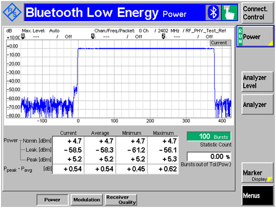 Rohde & Schwarz screen shot from output power test.
Key Figures for Bluetooth low energy Test Parameters
- Standard: Bluetooth 4.0 low energy
- Data rate: 1 Mbps.
- Modulation: GFSK with 250 kHz deviation.
- Min frequency: 2402 MHz.
- Mid frequency: 2440 MHz.
- Max frequency: 2480 MHz.
- TX output power:
- CC2540: 4 dBm (measured conducted at antenna connector)
- CC2541: 0 dBm (measured conducted at antenna connector)
- Min voltage: 2.0 V.
- Mid/nominal voltage: 3.0 V.
- Max voltage: 3.6 V.
- In-band image frequency:
- FRF + 2 MHz for FRF 2440 MHz
- FRF - 2 MHz for FRF > 2440 MHz
