Other Parts Discussed in Thread: CC2640, CC2630, , CC1350, CC2620, CC1310
Introduction
This article gives an overview of the available tools for designing a production test for a product by exercising the CC1310/CC1350 or CC2620/CC2630/CC2640/CC2650 devices. It also gives options for production programming of the Flash in these devices.
The purpose of the production test is to make sure that the assembled PCB is well functioning and meets the performance criteria for the finished product. It complements the production testing of each individual component of the board. It can be done manually, automatically, or a combination of the two. It can be done over operating conditions or just at nominal conditions. In all cases, the most common method for testing products based on a Wireless MCU is to make contact with the MCU from a production tester or PC, and exercise a representative subset of functionality and measure the result. A sequence of tests are performed, and based on the result, a product is deemed good or not good.
Production programming of an MCU is the process of transferring a binary code image into the Flash. This can either be the final application image, or a special image to be used during production testing. The most common options are to use a commercial production programming device, a serial bridge to a boot loader, or a JTAG emulator.
Production Testing
In addition to the standard MCU tests such as pin connections and power consumption, a Wireless MCU should include tests to ensure good RF performance of the assembly. It is important to ensure that the crystal(s), balun component(s), matching components and antenna are properly mounted and within allowed tolerances.
Depending on the quality requirements and targeted regulatory and standards specifications, testing of these parameters should include at least the following:
- RF packet reception of a signal close to targeted sensitivity level
- Measurement of transmitted RF signal (output power, frequency)
In addition, testing current consumption during receive and transmit operations can also reveal failing assemblies.
Test Setup
The CC13xx and CC26xx devices have three interfaces that are useful in production test:
- c-JTAG or JTAG
- Serial interface (UART or SPI)
- RF interface
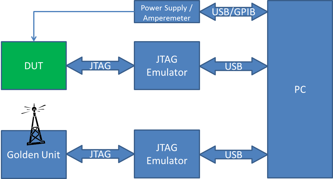
It is possible to design a test setup that does not require RF test equipment for each test setup. Instead, one can use a calibrated/compensated golden unit RF unit. The most common option is to use a TI evaluation module with the same Wireless MCU as the DUT (Device Under Test), or a similar device capable of communicating on the targeted RF frequency and modulation.

The Golden Unit and DUT are both controlled from the PC through JTAG emulators. A measuring power supply or similar is controlled from the same PC, and supplies the DUT and allows measurement of current consumption. Please see [CC13xx_CC26xx_Tools_Overview#Debuggers this page] for a list of supported emulators.
The PC-side software can be SmartRF Studio.
Scripting of SmartRFStudio is not supported for CC13xx/CC26xx, but a C++ libary is provided to enable integration of SmartRF Studio functionality into an automated test program. It provides a powerful interface to control both the DUT and the Golden Unit.
Prerequisites for compiling the application example.
- Microsoft Visual Studio C++ 2013 Express
- "Select Visual Studio 2013->Express 2013 for Desktop" under "Visual Studio downloads"
- Qt 5.5.0 installed on your computer
- Under the "Software" section of the SmartRF Studio page: "Qt 5.5.0 Source and Libraries for Windows (MSVC2013)"
The example project will be located here: C:\Texas Instruments\RadioTestLibrary-1.x.x\ide\windows\vc12\radio_test_lib_app_ex\radio_test_lib_app_ex.sln
Alternatives
For Bluetooth Low Energy devices under test, and alternative can be to use the [PTM Production Test Mode (PTM)] over UART in combination with a commercial Bluetooth tester with a Bluetooth Smart/Low Energy extension.
Production Programming
The CC13xx and CC26xx provide two interfaces for production Flash programming:
- c-JTAG/JTAG
- Serial Bootloader (UART or SPI)
Programming over JTAG
The XDS110/XDS200 in combination with the SmartRF Flash Programmer 2 PC tool is the recommended option. This tool includes a command line interface (CLI) that allows easy integration into a production program.
Commercial production programmers can represent significant increases in programming speed. The Elprotronic Flash Pro ARM has support for CC13xx and CC26xx and also offer a compatible socket board.
Programming over Serial Bootloader
The CC13xx and CC26xx have a built-in bootloader in ROM that supports communication over dedicated pins with a simple protocol. It also has functionality for an I/O backdoor that enables triggering of the bootloader even when there is already a valid image in Flash. The bootloader is documented in Chapter 9 of the Technical Reference Manual. It is supported by FlashProgrammer2 and can be run on the SmartRF06EB.
To disable in-field readout of flash contents, remember to disable the Bootloader in the CCFG configuration area in the device before shipping.


