Hi Sir,
During the production process of our BLE products, we found that the frequency deviation of the board that we produced is different from the sample board. The frequency deviation of the produced board have exceeded 200KHz. For some reasons, we cannot change the software. So I want to know if TI has provide some tools that can write the frequency offset configuration to the chip first, and then burn the program without changing the software.
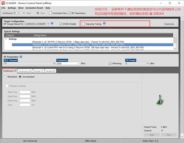
According to my experience, if the frequency offset is more than 200KHz, there should be a connection failure problem, but actually the product works well. So I want to know if there is a problem with my testing method. My testing method is as follows:
1) Testing method one
The configuration of the code is as follows:
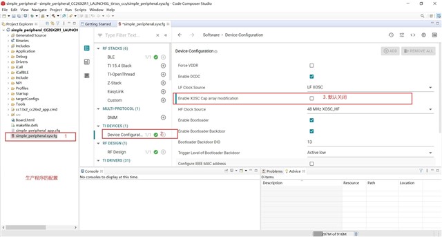
Set the configuration information of the fixed frequency tool, the program in the chip is deleted at this time.
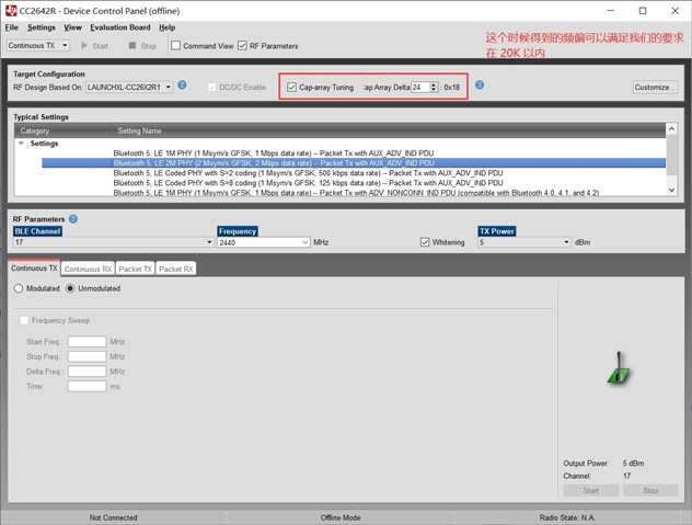
2) Testing method two
The configuration of the code is as follows:
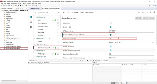
Set the configuration information of the fixed frequency tool, the program in the chip is deleted at this time.