This thread has been locked.

If you have a related question, please click the "Ask a related question" button in the top right corner. The newly created question will be automatically linked to this question.

CC2640 with 2-wire cJTAG CC-DEVPACK-DEBUG

Other Parts Discussed in Thread: CC2640, CC2650, ENERGYTRACE, UNIFLASH, CC2540, LAUNCHXL-CC2650, LAUNCHXL-CC1310

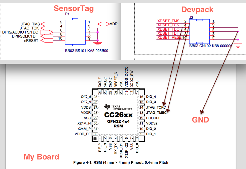
We made a custom board (very simple), using CC2640 4x4 and would like to know how to properly connect 2-wire cJTAG from CC-DEVPACK-DEBUG to it. 

We verified that the devpack can program the sensor tag but are having trouble getting it to recognize our board. 

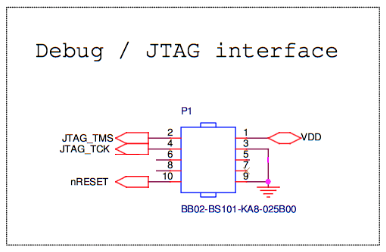
Attached is a drawing of the connections we made. 

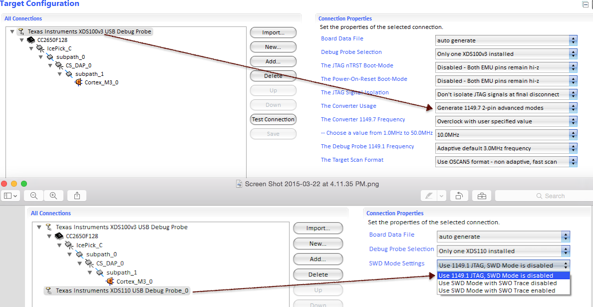
I believe the question comes down to is there is something that needs to be changed in the board configuration of the devpack in CCS (or IAR) to use cJTAG. it seems that by default it uses 4-wire JTAG when programing the sensor tag. 

can someone please clarify of A, our 3 wires (TMS, TCK, GND) are correct and suffice. and B, what change (if any) we need to make in the debugger configuration in CCS/IAR?

CCS is giving the following error when trying to connect to our board:

The controller cannot monitor the value on the EMU[0] pin. The controller cannot monitor the value on the EMU[1] pin. The controller cannot control the timing on output pins. The controller cannot control the timing on input pins. The scan-path link-delay has been set to exactly '0' (0x0000). An error occurred while hard opening the controller. -----[An error has occurred and this utility has aborted]-------------------- This error is generated by TI's USCIF driver or utilities. The value is '-242' (0xffffff0e). The title is 'SC_ERR_ROUTER_ACCESS_SUBPATH'. The explanation is: A router subpath could not be accessed. The board configuration file is probably incorrect.

  • I'm curious if the devpack (XDS110) can do 2-pin cJTAG? If i compare the available settings for XDS100v3 vs. XDS110 in CCS, i don't see an option for 2-pin 1149.7 for the XDS110, but i do for the XDS100v3. 

    I am wondering if this is because the devpack isn't fully supported yet in CCS or if the devpack can't do 2-pin cJTAG?

  • Hi Pixbroker,

    You should connect reset as well. I am looping in the tools guys for more details.

    Cheers,
    Fredrik
  • Pixbroker,

    The CC-DEVPACK-DEBUG hardware should support 2-pin cJTAG, but currently, only 4-pin JTAG has been implemented in the XDS110 drivers and CCS. I know that work is being done to get 2-pin cJTAG support in the drivers.

    Unfortunately, I do not know if there is a specific date for when 2-pin cJTAG support is avilable, but I will try to find out. Today you need TCK, TMS, TDO, TDI and RESET_N for XDS110 together with CC26xx devices.

    Br,
    TIABO 

  • Thanks for the feedback, although, disappointing. We are working on several CC26xx projects that are all very small boards and they don't have all the JTAG pins broken out, besides, use them as GPIO with peripherals connected, so we are relying on cJtag. 

    It would be great if you could find out an approximate ETA for 2-pin support in the drivers. Are we talking days, weeks, months? 

    As a side question, is SWO trace implemented yet?

    Thanks,

    -r

  • I have asked for an ETA on 2-pin support, I'll also try to get an ETA for SWO support and get back to you.

    Br,
    TIABO
  • Hi again,

    2-pin cJTAG support:
    Hopefully in mid May 2015. Driver support is expected in October release of SDO's emulation bundle.

    XDS110 SWO support:
    Drivers and HW support it today (via TDO pin). Getting it via other pins is expected ready together with 2-pin cJTAG.

    Br,
    TIABO

    Edited 2015-06-15.

  • Fredrik K said:
    You should connect reset as well.

    Can you clarify that reset is really necessary? The SmartRF06 documentation indicates that reset is optional.

    Additionally, the 1-pin debug header on the devpack does not have VDD_SENSE exposed. Where would one connect VDD_SENSE from target board to devpack?

  • TIABO said:
    Hi again,

    2-pin cJTAG support:
    Hopefully in mid May 2015.

    XDS110 SWO support:
    Drivers and HW support it today (via TDO pin). Getting it via other pins is expected ready together with 2-pin cJTAG.

    Br,
    TIABO

    Thanks for getting back to us so quickly. Seems like we will have to take al look at XDS200 for now. Thanks.

  • Hi,

    The reset signal is strictly speaking optional, but highly recommended for CC13xx and CC26xx devices. The reason is that the reset pin, combined with TCK toggling enables you to completely reset the device + halt the device before running any code in flash (halt-in-boot). All debuggers rely on having it available to gain access to the device.

    Br,
    TIABO
  • what about VDD_SENSE? is that required or is there a way to set ref voltage via software, if the voltage is known? 

    We are trying to reduce the number of pins we need to expose for programing due to board space restrictions. 

  • You can connect VDD sense to a separate supply if you the voltage of your DUT.

  • pixbroker,

    The CC-DEVPACK-DEBUG is designed for use with the CC2650 SensorTag, which is then powered by the CC-DEVPACK-DEBUG.

    CC-DEVPACK-DEBUG doesn't have any level shifter logic and expects the target to run at 3.3V.

    Br,
    TIABO

  • Hello Pixbroker,

    Have you done any research on a 10 pin to 10 pin cable to connect the debug dev pack to your board? On our board we have the same exact 10 pin header as P410 on the SmartRF06 board. We need to find a 10 pin female (plugs into our board) to 10-pin male cable (plugs into dev pack). We found one from Samtec, but the issue is that pin 1 comes out on the wrong side where it would connect to the debug dev pack. If you happen to have any info, it would be greatly appreciated.
  • If your male header on your board is exactly the same as on sensor tag, why can't you plug the devpack directly? if there is some obstruction that doesn't allow that, you may have to make your own extension cable as i am not aware of any that can be bough off the shelf. we made our own.
  • One option here (which I have done myself) is to desolder the female header from the DevPack Debug and solder a male header on the opposite side of the board. Works like a charm (but won´t fit directly on the SensorTag anymore of course).

  • Thanks for both of you replies. There are obstructions on our board which is why we can't plug it directly in. I would like to avoid modifying the Debug DevPack so it is easier for customers to use. The current solution I am using is two Samtec FFMD-05-T-04.00-01-N cables connected together. This allows us to get pin 1 in the right orientation. It would be cleaner to have one cable instead of stacking two, but it looks like the only option for now.

    Also, I saw the previous time estimate for cJTAG support was for mid May, has that been released yet or is it still in progress?
  • Hi,

    Is the 2-pin cjtag supported yet?
  • 2-pin cJTAG always worked, it is SWO/Trace via that interface that we are waiting on.
  • If I disconnect the TDO and TDI lines of my DebuDev pack from my CC2640, I cannot get SmartRF Programmer 2 or IAR to recognize my CC2640. As soon as I reconnect them to the CC2640 it works. Could you explain how to get cJTAG working with the DebugDev pack and those programs?
  • TIABO: "The CC-DEVPACK-DEBUG hardware should support 2-pin cJTAG, but currently, only 4-pin JTAG has been implemented in the XDS110 drivers and CCS. I know that work is being done to get 2-pin cJTAG support in the drivers.

    Unfortunately, I do not know if there is a specific date for when 2-pin cJTAG support is avilable, but I will try to find out. Today you need TCK, TMS, TDO, TDI and RESET_N for XDS110 together with CC26xx devices."

    The above comment seemed to suggest it was not supported? Glad to hear it works though.

  • Ryan Erickson said:
    Could you explain how to get cJTAG working with the DebugDev pack and those programs?

    I can't speak about the smart RF programer nor CCS, but if i connect the devpack to our board as per drawing below, it works for me with 2Pin cJtag in IAR. well, technically it's not 2 pins. it's 3 or if you count GND and VDD, it's actually 5.

    Note the 2 pins that are connected to GND. for some reason, without that, it doesn't work. no idea why.

    FWIW, we have since sold our devpack and switched to XDS200 for the better speed and SWO/Trace support.

  • Hi Cameron,

    cJTAG is not supported for the XDS110. During development it became clear that a timing constraint of the 110 prevents it from being able to operate in 2-pin mode.

    The XDS100 and XDS200 are alternatives that support cJTAG.

    Cheers,
    Fredrik
  • Hello,

    I've the same problem. I've read all the awsers and I don't have clear if finnaly you've get the solution. It is possible to use the devPack alone without the sensorTag forprogramming or debugging a CC2640? Which connections are necessary?

    I would be very helpful if someone clarify this.

    Best regards,
  • Yes, you can use the DevPack Debug as a stand-alone debugger. It does only support 4-pin JTAG so you need to connect TDI and TDO. You also need to replace the female 10-pin header or make some sort of adapter cable.

    Cheers,
    Fredrik
  • Fredrik K said:
    Yes, you can use the DevPack Debug as a stand-alone debugger. It does only support 4-pin JTAG so you need to connect TDI and TDO. You also need to replace the female 10-pin header or make some sort of adapter cable.

    Is the limitation to 4-pin JTAG specific to the Debug DevPack, or does it apply to all XDS110-class emulators? Or is the limitation in the CC26xx itself? The MSP432 launchpad has 2-pin JTAG output connections on J103, so I'm wondering whether I can use that to program a CC2650 (without SWO trace or anything fancy).

  • There are several threads on the e2e forum on this topic, see for instant e2e.ti.com/.../410451
  • See also processors.wiki.ti.com/.../CC13xx_CC26xx_Tools_Overview

    It is the XDS-110 that do not support the 2-pin JTAG, the CC26xx supports it. The SmartRFEB06 has the XDS100v3 which supports 2 pin JTAG
  • CHS said:
    There are several threads on the e2e forum on this topic, see for instant e2e.ti.com/.../410451

    Q: How do you keep a programmer in the shower all day?
    A: Give him a bottle of shampoo which says "lather, rinse, repeat." ;)

    (that link goes to the first page of this very thread!)

    CHS said:
    See also processors.wiki.ti.com/.../CC13xx_CC26xx_Tools_Overview

    It is the XDS-110 that do not support the 2-pin JTAG, the CC26xx supports it. The SmartRFEB06 has the XDS100v3 which supports 2 pin JTAG

    Although that link shows details for an XDS110 debugger, it seems to be specifically referring to the Debug DevPack shown in the picture. The "More about XDS110 link goes directly to the Debug DevPack page.

    I should have been less vague about this in my original post, but when I asked about XDS110-class debuggers I was particularly interested in the MSP‑EXP432P401R launchpad. This board has an XDS110-ET debugger, but it only exposes the SWDIO/SWCLK pins for 2-pin JTAG connection to targets other than the onboard MSP432.

    This thread suggests that the MSP‐EXP432P401R's XDS110-ET can support 2-pin JTAG, at least when connecting to another MSP432 target. If there's no obvious reason it won't work with the CC2650 then I'll try adapting a suitable cable to connect the launchpad to the SensorTag for debugging with EnergyTrace.

  • Hi,

    I believe the XDS110 supports 2-pin serial wire debug (SWD), but it currently does not support 2-pin cJTAG. So for CC26xx, you have to use 4-pin JTAG.

    Br,
    TIABO

  • TIABO said:

    I believe the XDS110 supports 2-pin serial wire debug (SWD), but it currently does not support 2-pin cJTAG. So for CC26xx, you have to use 4-pin JTAG.

    Ah, that makes sense now. I was mistakenly assuming that SWD was the same thing as cJTAG. They use the same pins but it seems the protocols differ.

    So the XDS110-ET doesn't support cJTAG, only JTAG and SWD. Meanwhile the CC26xx series doesn't support SWD, only JTAG and cJTAG. That leaves JTAG as the only option for this hardware combination.

    Here's a relevant part of the CC26xx TRM:

    The debug subsystem has only one slave DAP (CPU DAP). This debug port implements Serial Wire JTAG Debug Port (SWJ-DP) interface which allows external access to an Advanced High-performance Bus Access Port (AHB-AP) interface for debug accesses in the CPU.

    The SWJ-DP is a standard ARM® CoreSight™ debug port that combines JTAG-DP and Serial Wire Debug Port (SW-DP). Even though the SW-DP interface is supported by SWJ-DP, the CC26xx family does not use this mode. The key reason is that SW-DP becomes redundant for the design in the presence of the 2- pin JTAG (1149.7) mode.

    And finally, here's a link to a thread showing how to modify a MSP‑EXP432P401R to expose the full JTAG pinout: https://e2e.ti.com/support/wireless_connectivity/f/155/t/431666

  • Hi,

    Is the cJTAG support on XDS110 / CC-DEVPACK-DEBUG still on  track - so that there will be a driver release in October, as earlier indicated? 

  • Hi Teuvo,

    The latest information I have is that we are on track for October.

    Cheers,
    Fredrik
  • From what I read in the XDS Emulation Software release notes, the XDS110 firmware (2.2.5.1 or newer) now supports cJTAG. Does this mean this is possible using the CC-DEVPACK-DEBUG? I'm really hoping to get my Sensortag's SPI connections working while debugging / using the UART.

  • HI Arthur,

    You are right. If you update to the lates XDS FW it should default to cJTAG,

    Cheers,
    Fredrik

  • Fantastic! Does that mean that SPI (in particular the external flash) can be used while using the CC-DEVPACK-DEBUG? Or would that require hardware changes?
  • SPI should now work while debugging.
  • I've now done a bit of testing, but have been unable to get SPI, in particular the external flash, working once the XDS110 switches into runtime mode, i.e. it only works when I first plug the SensorTag + CC-DEVPACK-DEBUG into USB and the debugger is running in DFU mode. Of couse UART is not available in this mode, which is actually what interests me more than using the debugger.

    Ideally I'd like to have SPI (and UART) work immediately after flashing and resetting the CC2650 with SmartRF Flash Promgrammer 2.
  • Arthur,

    Sorry about the delayed reply. We have been able to reproduce an issue with the XDS110 in 2-pin cJTAG mode. What we observe is that while debugging in 2-pin cJTAG mode, no activity is seen on the CC2650 IO that is TDI in 4-pin mode. We have reported this as an issue and will get back with a solution as soon as it is available.

    Br,
    TIABO

  • Thank you for looking into this.

    Out of curiosity, I also just tested a CC-DEVPACK-DEBUG hw. rev. 1.3 with a SensorTag hw. rev. 1.2 and it does the same thing, i.e. no SPI.

    Is there, by any chance, a way to terminate the cJTAG connection in software after flashing?
  • Arthur Pitman said:
    Is there, by any chance, a way to terminate the cJTAG connection in software after flashing?

    No. The bug is that the XDS110 firmware drives the JTAG TDI pin in 2-pin cJTAG mode. Work is being done to fix, so hopefully a fix can be ready in not too long.

  • Hi TIABO,

    Could you provide a quick update on this issue? I have a board that doubles up SPI and TDI/TDO, thinking this was ok since cJTAG was supported on the XDS110.

    Should it work using the XDS100 v3?

    Thanks,
    --Allen
  • Yes, this should work on the XDS100v3, the issue is specific to XDS110.

    I don't have a progress update regarding the XDS TDI issue, unfortunately. 

    Br,
    TIABO 

  • +1

    I use XDS100v3 cJTAG mode to debug CC2640 for couple of months, it is fine.
  • Hello TIABO:

    Here is a section of my schematic that shows my connection from the CC2650 to my cJTAG connector
    I have a questions for you,  does the CC2650 needs the 32.768Khz crystal so the JTAG module inside can works? 

    Looking forward to hear from you.
    Regards

  • JTAG module does not run on 32kHz xtal.
    However if you are using PG2.2 or older version of our device, you need to have 32kHz xtal in place. For PG2.2 or older version of CC2650/CC2640, rcosclf shows glitches from time to time which causes system lock up, therefore a 32kHz xtal is needed to have the whole system functional.
  • Hello Mr. Lee

    Thank you for your answer. I reviewed the errata sheet for  CC2650/CC2640, and this is what it shows:

    I know this is a Reel´s label. 
    Considering that I have samples from TI, I have this kind of label:


    Can you please help me to identify if these sample are affected by this issue?

  • Those are PG2.2 since PG2.3 was not ready until later last year.

    You need to have 32kHz xtal on your board
  • OKay, I will add a 32kHz xtal on my board, once I have the board on my hands I will let you know if everything works propertly.
    Thank you Mr. Lee
  • TIABO said:
    No. The bug is that the XDS110 firmware drives the JTAG TDI pin in 2-pin cJTAG mode. Work is being done to fix, so hopefully a fix can be ready in not too long.

    Is there any news to report on this fix for XDS110 cJTAG?

  • Robert,

    No, this is still to be fixed. My apologies for this taking so long. The current workaround is to disconnect the TDI pin between the XDS110 and the target.

    TIABO