


Hi all,
I decided to write this more as a tutorial than a discussion.
I am working on my own custom board with CC2640 and I have a debugger XDS100V3 Rev C. by Olimex.
I wanted to run the example project UARTECHO that comes with TI-RTOS 2.13.00.06 (and other versions of TI-RTOS as well) on my CC2640.
I find this program important since it gives you the opportunity to quickly implement printing commands to and from your PC. This is of great value for debugging.
It took me many grueling hours to find out eventually how to run on this program on a custom board and with the Olimex XDS100V3 and I could have saved a lot of time if such a tutorial was available or if there was more documentation from Olimex (which there isn't) on how to set up a UART channel on a virtual com port that YOU need to create. So now that everything is up and running I wanted to share my solution so that all those out there who have a similar setup could benefit and save a lot of time.
By the way although I created my own custom board of CC2640, this tutorial is also relevant for those working with SensorTag (WITHOUT THE DEVPACK) or a custom board that has CC2650.
Let's begin.
Step 1: Importing the correct project
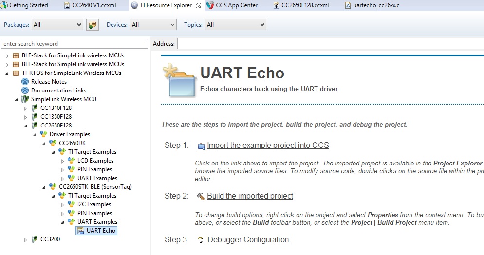
Let’s make sure you are using the correct example project since TI-RTOS comes with two example projects named UartEcho. You want to use the one that was designed to be used with the Sensor Tag and NOT THE RF06 Evaluation Board. See in the following image the project is marked in the explorer tree on the bottom left (this is under the TI Resource Explorer tab in Code Composer Studio 6.1):
After you’ve imported the project you can double check that you have the right project if you open the board.c file under the project tree (comment: in the image below you’ll see that the project name has a suffix “NOT_RF06” which I PERSONALLY ADDED. Originally the project name didn’t have that suffix). You’ll see that the unshaded part in the definitions part has an include path “<ti/boards/SensorTag/CC26XXST_0120/Board.c>” (I emphasized the word "SensorTag").
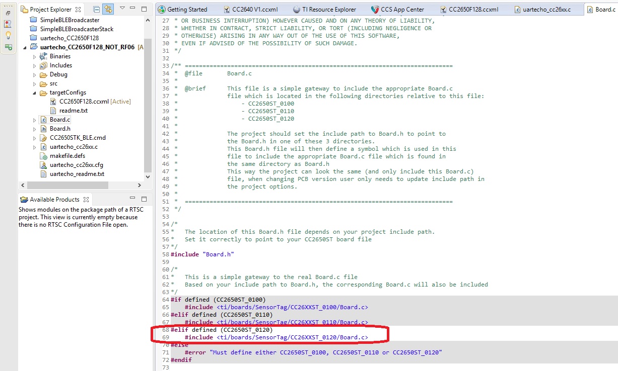
If you imported the WRONG project you’ll see “<ti/boards/SRF06EB/CC2650EM_7ID/Board.c>” (I emphasized the SRF06EB).
Good. Now there is no need to change anything in the project itself unlike it was said in other discussions in the forum. But in those other discussions the module was being debugged using DEVPACK with SensorTag and as I mentioned in the beginning, this tutorial is for those NOT using DEVPACK with Sensortag.
Step 2: Setting up the debugger
This was for me the real tricky part. Olimex’s documentation is very very poor when it comes to setting up a UART channel. I had to rely and cross reference multiple documents and schematics from TI and Olimex in order to finally understand how to set everything up properly.
First connect the debugger (XDS100V3) to your PC USB port. Let’s set up a virtual com port in order to use the UART. Simply follow the instructions from the following link:
Note:
In the link refer to the question “How can I use the XDS100v2's second port as a serial port (UART)?”
Notice that in the link they talk about XDS100V2 but in the end V3 is very similar to V2 except that V3 supports also IEEE 1149.7.
Just follow those instructions and you'll get the COM port up and running.
After you’ve got the COM Port up and running, now let’s configure the Olimex XDS100V3 debugger.
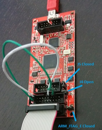
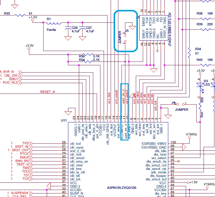
- Make sure that jumper J5 is closed (this enables UART) and that J4 must be open (not needed).
- Source for this is from TI’s release of board design files for XDS100V3 [registration required]. Once downloaded, install the package and then within the package search for the file titled “512992b2_xds100v3r_aug30_2011.pdf”. This is the recommended schematic for the board. And J5 can is what enables UART.
- Source for this is from TI’s release of board design files for XDS100V3 [registration required]. Once downloaded, install the package and then within the package search for the file titled “512992b2_xds100v3r_aug30_2011.pdf”. This is the recommended schematic for the board. And J5 can is what enables UART.
- Also, since we are going to use the ARM_JTAG 20 pin connector and NOT the TI_JTAG then we need to close the jumper ARM_JTAG_E (Source: Olimex XDS100V3 Rev. C datasheet paragraph 4.5.1)
- You can see in the picture of my XDS100V3 a white and green wire – I will get to that near the end.
In order to connect the XDS100V3 to the SensorTag OR to a custom board we will be using the MDL-ADA2 10-pin to 20-pin JTAG Adapter Module. It can be bought from the TI Store, Mouser, DigiKey, etc.
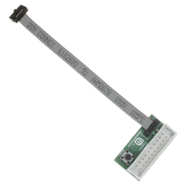
Here is the schematic:

Connect the cable to the SensorTag here:

If you have your own custom board connect the cable to the 10-pin ARM Cortex JTAG connector on your board.
The full connection link should look like this (for SensorTag):

Now finally, in order to allow the UART to work I tried to follow the same instructions as written on page 33 in the document Getting Started Guide for TI-RTOS 2.12 for SimpleLink™ Wireless MCUs (document name spruhu8c.pdf can be found at: http://www.ti.com/lit/ug/spruhu8c/spruhu8c.pdf).
I quote from page 33:
“For the UART Echo example, the SensorTag's UART data pins are multiplexed with the JTAG_TDO and JTAG_TDI pins. On the SmartRF06 development board, these pins need to be rerouted from the JTAG debugger to the onboard UART - USB converter (XDS100v3) using jumper bypasses as shown in the photo and schematic diagram below.”
However, since the instructions there are for the RF06 evaluation board I had to dig further and understand how to reroute the TDO and TDI lines.
So I figured that all I had to do was find the schematics for the connectors of the XDS100V3 of Olimex and reroute the TDO and TDI lines similarly to the example shown for the RF06 EVM.
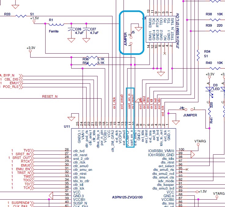
After searching a bit online I found the schematics for the connectors of the Olimex XDS100V3:
Here I already marked the two pair of pins that need to be connected (one pair is marked in blue and the second is marked in orange). This is how I connected the white and green wires seen on my XDS100V3 board earlier.

Step 3: Debug Mode and Serial Monitor
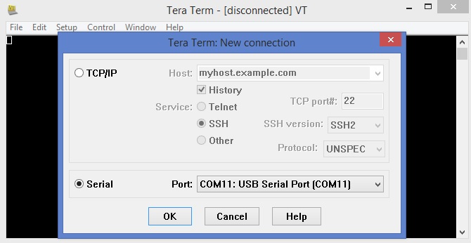
Simply build the project and enter debug mode. Then open a terminal (I used Tera Term) and make sure you select the virtual com port you set up previously. Everybody can get a different number for the virtual com port. In the image below my number is 11 but you could get a different number.
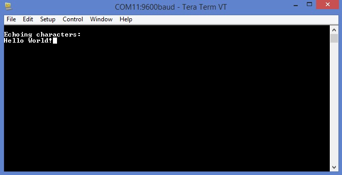
Then run the program and you should see on the serial monitor “Echoing Characters:”.
Begin typing and you’ll see the characters displayed on the monitor. Walla, you’re done :)
Cheers,
Eyal

